
3.2: Resistance and Energy Dissipation
- Page ID
- 21516

\( \newcommand{\vecs}[1]{\overset { \scriptstyle \rightharpoonup} {\mathbf{#1}} } \)
\( \newcommand{\vecd}[1]{\overset{-\!-\!\rightharpoonup}{\vphantom{a}\smash {#1}}} \)
\( \newcommand{\dsum}{\displaystyle\sum\limits} \)
\( \newcommand{\dint}{\displaystyle\int\limits} \)
\( \newcommand{\dlim}{\displaystyle\lim\limits} \)
\( \newcommand{\id}{\mathrm{id}}\) \( \newcommand{\Span}{\mathrm{span}}\)
( \newcommand{\kernel}{\mathrm{null}\,}\) \( \newcommand{\range}{\mathrm{range}\,}\)
\( \newcommand{\RealPart}{\mathrm{Re}}\) \( \newcommand{\ImaginaryPart}{\mathrm{Im}}\)
\( \newcommand{\Argument}{\mathrm{Arg}}\) \( \newcommand{\norm}[1]{\| #1 \|}\)
\( \newcommand{\inner}[2]{\langle #1, #2 \rangle}\)
\( \newcommand{\Span}{\mathrm{span}}\)
\( \newcommand{\id}{\mathrm{id}}\)
\( \newcommand{\Span}{\mathrm{span}}\)
\( \newcommand{\kernel}{\mathrm{null}\,}\)
\( \newcommand{\range}{\mathrm{range}\,}\)
\( \newcommand{\RealPart}{\mathrm{Re}}\)
\( \newcommand{\ImaginaryPart}{\mathrm{Im}}\)
\( \newcommand{\Argument}{\mathrm{Arg}}\)
\( \newcommand{\norm}[1]{\| #1 \|}\)
\( \newcommand{\inner}[2]{\langle #1, #2 \rangle}\)
\( \newcommand{\Span}{\mathrm{span}}\) \( \newcommand{\AA}{\unicode[.8,0]{x212B}}\)
\( \newcommand{\vectorA}[1]{\vec{#1}} % arrow\)
\( \newcommand{\vectorAt}[1]{\vec{\text{#1}}} % arrow\)
\( \newcommand{\vectorB}[1]{\overset { \scriptstyle \rightharpoonup} {\mathbf{#1}} } \)
\( \newcommand{\vectorC}[1]{\textbf{#1}} \)
\( \newcommand{\vectorD}[1]{\overrightarrow{#1}} \)
\( \newcommand{\vectorDt}[1]{\overrightarrow{\text{#1}}} \)
\( \newcommand{\vectE}[1]{\overset{-\!-\!\rightharpoonup}{\vphantom{a}\smash{\mathbf {#1}}}} \)
\( \newcommand{\vecs}[1]{\overset { \scriptstyle \rightharpoonup} {\mathbf{#1}} } \)
\(\newcommand{\longvect}{\overrightarrow}\)
\( \newcommand{\vecd}[1]{\overset{-\!-\!\rightharpoonup}{\vphantom{a}\smash {#1}}} \)
\(\newcommand{\avec}{\mathbf a}\) \(\newcommand{\bvec}{\mathbf b}\) \(\newcommand{\cvec}{\mathbf c}\) \(\newcommand{\dvec}{\mathbf d}\) \(\newcommand{\dtil}{\widetilde{\mathbf d}}\) \(\newcommand{\evec}{\mathbf e}\) \(\newcommand{\fvec}{\mathbf f}\) \(\newcommand{\nvec}{\mathbf n}\) \(\newcommand{\pvec}{\mathbf p}\) \(\newcommand{\qvec}{\mathbf q}\) \(\newcommand{\svec}{\mathbf s}\) \(\newcommand{\tvec}{\mathbf t}\) \(\newcommand{\uvec}{\mathbf u}\) \(\newcommand{\vvec}{\mathbf v}\) \(\newcommand{\wvec}{\mathbf w}\) \(\newcommand{\xvec}{\mathbf x}\) \(\newcommand{\yvec}{\mathbf y}\) \(\newcommand{\zvec}{\mathbf z}\) \(\newcommand{\rvec}{\mathbf r}\) \(\newcommand{\mvec}{\mathbf m}\) \(\newcommand{\zerovec}{\mathbf 0}\) \(\newcommand{\onevec}{\mathbf 1}\) \(\newcommand{\real}{\mathbb R}\) \(\newcommand{\twovec}[2]{\left[\begin{array}{r}#1 \\ #2 \end{array}\right]}\) \(\newcommand{\ctwovec}[2]{\left[\begin{array}{c}#1 \\ #2 \end{array}\right]}\) \(\newcommand{\threevec}[3]{\left[\begin{array}{r}#1 \\ #2 \\ #3 \end{array}\right]}\) \(\newcommand{\cthreevec}[3]{\left[\begin{array}{c}#1 \\ #2 \\ #3 \end{array}\right]}\) \(\newcommand{\fourvec}[4]{\left[\begin{array}{r}#1 \\ #2 \\ #3 \\ #4 \end{array}\right]}\) \(\newcommand{\cfourvec}[4]{\left[\begin{array}{c}#1 \\ #2 \\ #3 \\ #4 \end{array}\right]}\) \(\newcommand{\fivevec}[5]{\left[\begin{array}{r}#1 \\ #2 \\ #3 \\ #4 \\ #5 \\ \end{array}\right]}\) \(\newcommand{\cfivevec}[5]{\left[\begin{array}{c}#1 \\ #2 \\ #3 \\ #4 \\ #5 \\ \end{array}\right]}\) \(\newcommand{\mattwo}[4]{\left[\begin{array}{rr}#1 \amp #2 \\ #3 \amp #4 \\ \end{array}\right]}\) \(\newcommand{\laspan}[1]{\text{Span}\{#1\}}\) \(\newcommand{\bcal}{\cal B}\) \(\newcommand{\ccal}{\cal C}\) \(\newcommand{\scal}{\cal S}\) \(\newcommand{\wcal}{\cal W}\) \(\newcommand{\ecal}{\cal E}\) \(\newcommand{\coords}[2]{\left\{#1\right\}_{#2}}\) \(\newcommand{\gray}[1]{\color{gray}{#1}}\) \(\newcommand{\lgray}[1]{\color{lightgray}{#1}}\) \(\newcommand{\rank}{\operatorname{rank}}\) \(\newcommand{\row}{\text{Row}}\) \(\newcommand{\col}{\text{Col}}\) \(\renewcommand{\row}{\text{Row}}\) \(\newcommand{\nul}{\text{Nul}}\) \(\newcommand{\var}{\text{Var}}\) \(\newcommand{\corr}{\text{corr}}\) \(\newcommand{\len}[1]{\left|#1\right|}\) \(\newcommand{\bbar}{\overline{\bvec}}\) \(\newcommand{\bhat}{\widehat{\bvec}}\) \(\newcommand{\bperp}{\bvec^\perp}\) \(\newcommand{\xhat}{\widehat{\xvec}}\) \(\newcommand{\vhat}{\widehat{\vvec}}\) \(\newcommand{\uhat}{\widehat{\uvec}}\) \(\newcommand{\what}{\widehat{\wvec}}\) \(\newcommand{\Sighat}{\widehat{\Sigma}}\) \(\newcommand{\lt}{<}\) \(\newcommand{\gt}{>}\) \(\newcommand{\amp}{&}\) \(\definecolor{fillinmathshade}{gray}{0.9}\)Resistivity
We said in the previous section that electric charge flow is caused by the applied electric field, and that what happens to the charges similar to air resistance, inasmuch as a “terminal velocity” is reached (in the case of electricity, this is the drift velocity). We know that increasing the electric field increases the drift velocity and with it the current density, but the exact relationship is not obvious. With experimentation (and/or theoretical models beyond the scope of this course), we find that in fact the electric field vector and the current density vector are directly proportional:
\[ \overrightarrow E = \left(constant\right) \overrightarrow J \]
it makes sense that these two vectors would point in the same direction, since the current is defined as the direction of positive charge flow. The constant of proportionality is called the resistivity, and is represented by the Greek letter \(\rho\):
\[ \overrightarrow E = \rho\; \overrightarrow J \]
This relation is known as Ohm's law.
Alert
It is common in physics to occasionally see a collision of the same variable used for more than one quantity, such as \(T\) for period and temperature, or \(V\) for volume and electrostatic potential. But the collision of the use of \(\rho\) in Physics 9C is perhaps the most annoying. This letter appears in multiple equations involving density – in the drift velocity definition and continuity equation where it represents charge density, and in Ohm's law where it represents current density. Physicists are not bothered by this because they keep the context of equations fresh in their minds, but students encountering these equations for the first time – especially so close together – can find it daunting. The solution is to learn to think of equations in context, keeping a physical system in mind, rather than thinking of them as a jumble of incomprehensible variables.
A quick look at the equation for Ohm's law shows that the greater the resistivity, the less that the moving charges react to the electric field. So what physical properties play a role in this "friction" effect? There are essentially two things that play a role in resistivity, both of them related to the material through which the charge is flowing:
- its molecular structure
- its temperature
The molecular structure comes into play in ways that are impossible to describe in detail without a background in quantum physics. But there are two main ways that the specifics of the type of material involved comes into play. The first is how many free electrons the material allows – all else being equal, the resistivity is lower when more free charge is available. Conductors provide lots of free electrons, semiconductors far fewer, and insulators essentially none. Among conductors, it turns out that the more "regular" (or maybe the word "predictable" is more descriptive) the lattice of fixed nuclei is, the better it conducts (i.e. the lower the resistivity). Metals that are alloys (mixes of different elements) have their atomic nuclei arranged more haphazardly, and therefore have higher resistivities.
The effect of temperature on resistivity for a given material is more intuitive. Recall that what slows the electrons is collisions with atomic nuclei in the lattice of the material. These atoms are constantly vibrating, the energy of which is determined by the temperature of the material. When the temperature rises in a conductor, the more violent vibrations of these obstacles results in more collisions (again, the lattice structure is less "predictable"). So for conductors, the resistivity goes up as the temperature rises. Interestingly, for semiconductors the opposite is true – an increase in temperature results in a lower resistivity. The reason for this is that the resistivity in semiconductors is mostly due to the low number of free electrons. When the temperature is raised, many of the bound electrons gain energy, and tear themselves free. So while the vibrating atoms in the lattice still create more collisions in a semiconductor, the increase in the number of available free electrons is a far more important factor, and the resisitivity goes down.
We can approximate the reaction of resistivity to temperature with a linear relationship. If we measure the resistivity of a material at temperature \(T_o\) to be \(\rho_o\), then the resistivity at a new temperature \(T\) is given by:
\[\rho\left(T\right) = \rho_o\left[1+\alpha\left(T-T_o\right)\right] \]
The constant \(\alpha\) is called the coefficient of resistivity. We are not unfamiliar with linear approximations of physical properties like this one. For example, we saw something very similar (it also involved temperature!) in the case of thermal expansion in Physics 9B.
Resistance
As is usually the case, it is easier to deal with scalar energies than with vector forces, so we seek a way to get away from our use of electric field and current density. To discuss energy, we need to shift over to using electrostatic potential rather than electric field. Consider the simple physical system that consists of a cylindrical conductor with a cross-sectional area \(A\), a length \(L\), and a potential difference \(V_A-V_B\) (recall that we no longer consider conductors to be equipotentials):
Figure 3.2.1 – Conducting Cylinder
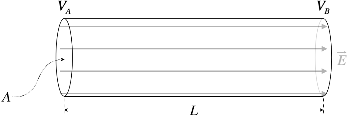
We can now relate the potential difference to the constant electric field, which we can then relate to the current density via Ohm's law, and the current density can then be related to the electric current:
\[\left. \begin{array}{l} V_A-V_B = \int\limits_A^B \overrightarrow E\cdot\overrightarrow{dl} = E\cdot L && \Rightarrow && E =\dfrac{V}{L} \\ E=\rho\;J && \Rightarrow && E = \rho\dfrac{I}{A} \end{array} \right\}\;\;\; V=I\left(\dfrac{\rho L}{A}\right) = IR\]
The quantity \(R \equiv \frac{\rho L}{A}\) contains all the information about the conductor needed to determine the current from the voltage difference: its length, cross-sectional area, and resistivity. This value \(R\) is called the resistance of the conductor. Its units can be easily determined from the equation above – they are volts per amp. This unit is given is own name – ohms (\(\Omega\)). This equation that relates voltage drop, current, and resistance is just a simplified version of Ohm's law, and is usually referred to by the same name (we will do so henceforth).
Power
From this energy perspective, we can see that the charge drops in potential energy when it goes from the higher potential to the lower (okay, technically, it is the negatively-charged electrons that go from lower potential to higher, but that is still a decrease in potential energy). But we also know that the drift velocity doesn’t change, so the lost potential energy doesn’t go into kinetic energy. Where does it go? Like air friction, electrical resistance results in energy being converted to thermal energy. This means that the conductor with resistance will get hotter as current flows through it.
As we are now talking about flowing charge, it is easier to talk about the rate at which energy is converted from electrical potential energy to thermal energy. We know that when a charge \(q\) drops through the potential \(V\), it loses a potential energy equal to \(U=qV\). The rate at which this occurs (i.e. the power) is the time rate of change of this. Since the voltage remains fixed, we have:
\[P = \frac{d}{dt}\left(qV\right) = \frac{dq}{dt}V = IV\]
We can use Ohm's law to express this relation in two other ways:
\[P = IV = I^2R = \dfrac{V^2}{R}\]
This set of equations for power bear a striking resemblance to the set of equations for potential energy in a capacitor given in Equations 2.4.11 (with the exception of the absence of a factor of \(\frac{1}{2}\) everywhere). Like those equations, the choice of which of these expressions to use will often depend upon what quantities are unchanging in the physical situation. For example, if you increase the resistance and put the same voltage across it, you find that the rate of energy conversion to thermal is lower. But if instead the current is held fixed, the rate of energy conversion to thermal is increased with an increase in resistance.
Alert
One of the most common examples we will use in discussing power in electrical circuits is the light bulb, as it provides a nice visual manifestation of the conversion of electrical energy to another form that exits the circuit. Using our formulas for power, it is clear that the power ceases to be converted the moment that the current stops flowing, but one might notice that (for example) an incandescent light bulb continues to glow a short time after the connection is broken. This does not mean that the current continues flowing for a short time afterward – as far as we are concerned, the current ceases essentially immediately. The continued glow comes from the fact that the glow originates from the increased temperature of the filament, and cutting the current then allows the filament to cool at whatever rate is natural for it to cool in its surroundings, so the (visible) light goes out only when it gets below a certain temperature. This lag in the cooling time of the filament is responsible for the light going out slowly; it is not a lag in the diminishment of the current.