2.6: Incidence at an Arbitrary Angle.


- Last updated
- Mar 5, 2022
- Save as PDF

( \newcommand{\kernel}{\mathrm{null}\,}\)
In Section 4 (Incidence at the Brewster Angle) it became clear that the reflection of light polarized in the plane of incidence was different from the reflection of plane polarized light polarized at right angles to the plane incidence. Therefore it makes sense, in this section, to consider the two planes of polarization separately. I shall suppose that both media are isotropic (i.e. not birefringent).
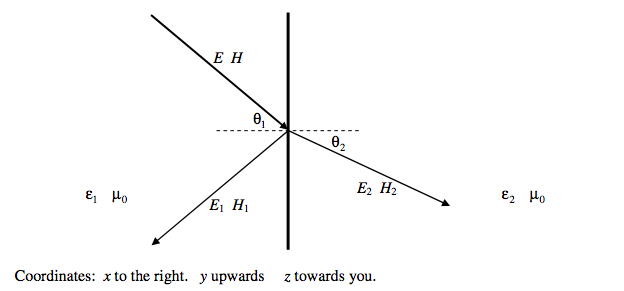
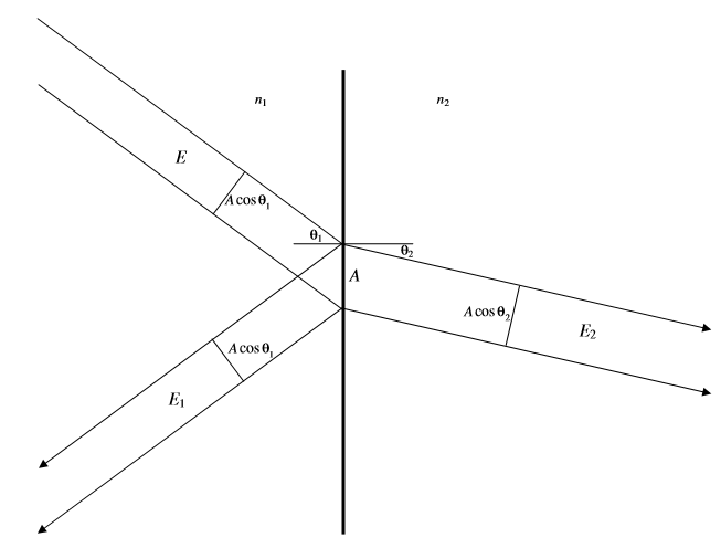
In the following discussion, we’ll suppose that light is travelling from a medium of permittivity \epsilon_1 to a medium of greater permittivity \epsilon_2. Both permeabilities are equal, and close to \mu_0. The electric and magnetic fields of the incident wave will be denoted by E and H. The electric and magnetic fields of the reflected wave will be denoted by E_1 and H_1. The electric and magnetic fields of the transmitted wave will be denoted by E_2 and H_2. (And in case you are wondering, by H I mean H, and by B I mean B.)
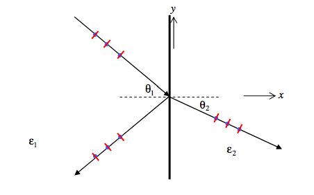
We’ll start by supposing that the incident light is plane polarized with the electric field perpendicular (senkrecht) to the plane of incidence. That is, the electric field has only a z-component. The oscillating electric field E is indicated by blue dots, and the magnetic field H by red dashes in the drawing below.
The boundary conditions are: For the tangential (z) component of \mathbf{E}
E + E_1 = E_2\tag{9}\label{eq:2.9}
For the tangential (y) component of \mathbf{H}
(H-H_1)\cos\theta_1 = H_2 \cos \theta_2. \tag{10}\label{eq:2.10}
That is,
\dfrac{(E-E_1)}{Z_1}\cos\theta_1 = \dfrac{E_2}{Z_2}\cos \theta_2, \tag{11}\label{eq:2.11}
or
n_1(E-E_1)\cos\theta_1 = n_2E_2\cos\theta_2. \tag{12}\label{eq:2.12}
Eliminate E_2 between Equations \ref{eq:2.9} and \ref{eq:2.12}:
Reflected amplitude:
\dfrac{E_1}{E} = \dfrac{n_1\cos\theta_1 - n_2\cos\theta_2}{n_1\cos\theta_1+n_2\cos\theta_2}. \tag{13}\label{eq:2.13}
Use Equation \ref{eq:2.9}:
Transmitted amplitude
\dfrac{E_2}{E} = \dfrac{2n_2\cos\theta_1}{n_1\cos\theta_1+n_2\cos\theta_2}. \tag{14}\label{eq:2.14}
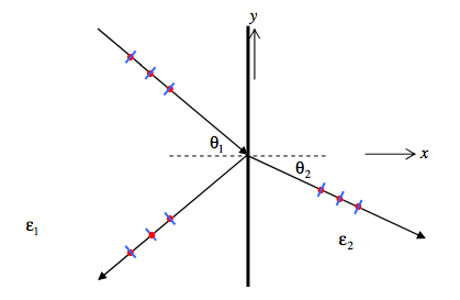
Now we’ll supposing that the incident light is plane polarized with the electric field parallel to the plane of incidence. This, it is the magnetic field that has only a z-component. The oscillating electric field E is indicated by blue dashes, and the magnetic field H by red dots in the drawing below.
The boundary conditions are:
For the tangential (z) component of \mathbf{H}
H+H_1 = H_2
That is:
\dfrac{E+E_1}{Z_1} = \dfrac{E_2}{Z_2} \, \text{or} \, n_1(E+E_1) = n_2E_2. \tag{15}\label{eq:2.15}
For the tangential (y) component of \mathbf{E}
(E- E_1) \cos \theta_1 = E_2\cos\theta_2. \tag{16}\label{eq:2.16}
Eliminate E_2 between Equations \ref{eq:2.15} and \ref{eq:2.16}:
Reflected amplitude:
\dfrac{E_1}{E} = \dfrac{n_2\cos\theta_1 -n_1\cos\theta_2}{n_2\cos\theta_1+n_1\cos\theta_2}.\tag{17}\label{eq:2.17}
Use Equation \ref{eq:2.15}:
Transmitted amplitude:
\dfrac{E_2}{E} = \dfrac{2n_1\cos\theta_1}{n_2\cos\theta_1+n_1\cos\theta_2}. \tag{18}\label{eq:2.18}
These are the Fresnel Equations, gathered together below:
Perpendicular (Senkrecht)
Reflected amplitude:
\dfrac{E_1}{E} = \dfrac{n_2\cos\theta_1 -n_2\cos\theta_2}{n_2\cos\theta_1+n_2\cos\theta_2}.
Transmitted amplitude:
\dfrac{E_2}{E} = \dfrac{2n_1\cos\theta_1 }{n_1\cos\theta_1+n_2\cos\theta_2}.
Parallel
Reflected amplitude:
\dfrac{E_{1}}{E}\ =\ \dfrac{n_{2}\cos\theta_{1}\ -n_{1}\cos\theta_{2}}{n_{2}\cos\theta_{1}\ +n_{1}\cos\theta_{2}}.
Transmitted amplitude:
\dfrac{E_{2}}{E}\ =\ \dfrac{2n_{1}\cos\theta_{1}}{n_{2}\cos\theta_{1}\ +n_{1}\cos\theta_{2}}.
They evidently depend only on the ratio of the refractive indices (i.e. the refractive index of one medium relative to that of the other). If we write n= n_2/n_1, the equations become
Perpendicular (Senkrecht)
Reflected amplitude:
\dfrac{E_{1}}{E} = \dfrac{\cos\theta_{1} -n\cos\theta_{2}}{\cos\theta_{1} +n\cos\theta_{2}}.
Transmitted amplitude:
\dfrac{E_{2}}{E}\ =\ \dfrac{2\cos\theta_{1}}{\cos\theta_{1}\ +n\cos\theta_{2}}.
Parallel
Reflected amplitude:
\dfrac{E_{1}}{E} = \dfrac{n\cos\theta_{1} -\cos\theta_{2}}{n\cos\theta_{1} +\cos\theta_{2}}.
Transmitted amplitude:
\dfrac{E_{2}}{E}\ =\ \dfrac{2\cos\theta_{1}}{n\cos\theta_{1}\ +\cos\theta_{2}}.
For normal incidence, the ratios for the senkrecht component become \dfrac{1\ -\ n}{1\ +\ n} and \dfrac{2}{1\ +\ n} as expected. The ratios for the parallel component, however, become \dfrac{n\ -\ 1}{n\ +\ 1} and \dfrac{2}{1\ +\ n}, apparently predicting no phase change at external reflection for the parallel component. This is only apparent, however, and the explanation for the apparent anomaly is given on pp. 20-24.
It will be noted that n,\ \theta_{1},\ \theta_{2} are also related by Snell’s law: \sin\theta_{1}\ =\ n\sin\theta_{2}, so that we can eliminate n from Fresnel’s equations in order to express them in terms of the angles of incidence and refraction only. If this is done we obtain:
Perpendicular (Senkrecht):
Reflected amplitude:
\dfrac{E_{1}}{E}\ =\ -\dfrac{\sin(\theta_{1}\ -\theta_{2})}{\sin(\theta_{1}\ +\theta_{2})}.
Transmitted amplitude:
\dfrac{E_{2}}{E}\ = \dfrac{2\sin\theta_{2}\cos\theta_{1}}{\sin(\theta_{1}+\theta_{2})}\ =\ \frac{2}{1\ +\frac{\tan\theta_{1}}{\tan\theta_{2}}}.
Parallel
Reflected amplitude:
\dfrac{E_{1}}{E}\ =\ -\dfrac{\tan(\theta_{1}\ -\theta_{2})}{\tan(\theta_{1}\ +\theta_{2})}.
Transmitted amplitude:
\dfrac{E_{2}}{E}\ = \dfrac{2\sin\theta_{2}\cos\theta_{1}}{\sin(\theta_{1}+\theta_{2})\cos(\theta_{1}\ -\theta_{2})}.
In perhaps the most useful form of all, we could eliminate \theta_{2} from the Fresnel equations and hence obtain them as functions of \theta_{1} and n only. This will enable us easily to calculate the reflected and transmitted amplitudes in terms of the angle of incidence. Thus:
Perpendicular (Senkrecht)
Reflected amplitude:
\dfrac{E_{1}}{E}\ =\ -\dfrac{(n^{2}\ -\sin^{2}\theta_{1})^{\frac{1}{2}}\ -\cos\theta_{1}}{(n^{2}\ -\sin^{2}\theta_{1})^{\frac{1}{2}}\ +\cos\theta_{1}}
Transmitted amplitude:
\dfrac{E_{2}}{E}\ =\ -\dfrac{2\cos\theta_{1}}{(n^{2}\ -\sin^{2}\theta_{1})^{\frac{1}{2}}\ +\cos\theta_{1}}.
Parallel
Reflected amplitude:
\dfrac{E_{1}}{E}\ =\dfrac{n^{2}\cos\theta_{1}\ -(n^{2}\ -\sin^{2}\theta_{1})^{\frac{1}{2}}}{n^{2}\cos\theta_{1}\ +(n^{2}\ -\sin^{2}\theta_{1})^{\frac{1}{2}}}.
Transmitted amplitude:
\dfrac{E_{2}}{E}\ =\ \dfrac{2n\cos\theta_{1}}{n^{2}\cos\theta_{1}+(n^{2}-\sin^{2}\theta_{1})^{\frac{1}{2}}}.
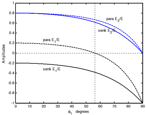
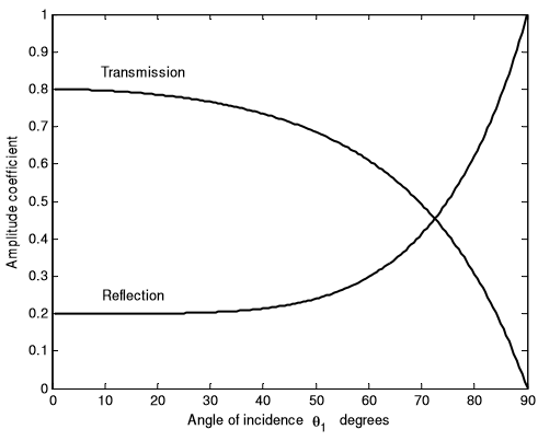
Black curves are the amplitudes of the reflected waves.
Blue curves are the amplitudes of the transmitted waves.
Continuous curves are for senkrecht (perpendicular) waves.
Dashed curves are for parallel waves.
Negative values show where there is a 180º phase shift on reflection. Notice that, at the Brewster angle (about 56º), none of the parallel component is reflected.
At 90º (grazing incidence) no light is transmitted; it is all reflected, but with a phase change (negative amplitude).
Energy considerations
Recall that for the parallel component, the incident, reflected and transmitted amplitudes are in the ratio
E \quad:\quad E_{1} \quad : \quad E_{2}=1 \quad : \quad -\dfrac{(n^{2}-\sin^{2}\theta_{1})^{\frac{1}{2}}-\cos\theta_{1}}{(n^{2}-\sin^{2}\theta_{1})^{\frac{1}{2}}+\cos\theta_{1}} \quad : \quad \dfrac{2\cos\theta_{1}}{(n^{2}-\sin^{2}\theta_{1})^{\frac{1}{2}}+\cos\theta_{1}}
and for the senkrecht component they are in the ratio
E \quad:\quad E_{1} \quad : \quad E_{2}=1 \quad : \quad \dfrac{n^{2}\cos\theta_{1}-(n^{2}-\sin^{2}\theta_{1})^{\frac{1}{2}}}{n^{2}\cos\theta_{1}+(n^{2}-\sin^{2}\theta_{1})^{\frac{1}{2}}} \quad : \quad \dfrac{2\cos\theta_{1}}{n^{2}\cos\theta_{1}+(n^{2}-\sin^{2}\theta_{1})^{\frac{1}{2}}}
(Here n\ =\ \dfrac{n_{2}}{n_{1}}.)
Suppose that the incident light strikes the interface in an area A. That means that the incident and reflected light are each in beams of cross-sectional area A\cos\theta_{1}, and the transmitted light is in a beam of cross-sectional area A_{2}. We are going to calculate the ratio P \quad : \quad P_{1} \quad: \quad P_{2} of the rate of transmission of energy (power) in each beam; and if we do our algebra correctly, we should find that P_{1}\ +\ P_{2}\ =\ P.
Recall that the energy per unit volume in an electric field is proportional to \epsilon E^{2}, where \epsilon, the permittivity, is proportional to the square of the refractive index. The power transmitted by each beam is proportional to the energy per unit volume, times the speed of transmission (which is inversely proportional to the refractive index), and to the crosssection area of the beam.
Therefore, for the parallel component and for the senkrecht component,
P\ \ :\ \ P_{1} \ \ :\ \ P_{2}=n_{1}E^{2}\cos\theta_{1} \ \ :\ \ n_{1}E_{1}^{2}\cos\theta_{1} \ \ :\ \ n_{2}E_{2}^{2}\cos\theta_{2}
Normalizing this expression so that P\ =\ 1, we obtain
P\ \ :\ \ P_{1} \ \ :\ \ P_{2}=1 \ \ :\ \ \left(\dfrac{E_{1}}{E}\right)^{2} \ \ :\ \ n\left(\dfrac{E_{2}}{E}\right)^{2}\dfrac{\cos\theta_{2}}{\cos\theta_{1}}.
These are shown below for n = 1.5, and indeed P_{1}\ +\ P_{2}\ =\ P for each component, and energy is conserved.
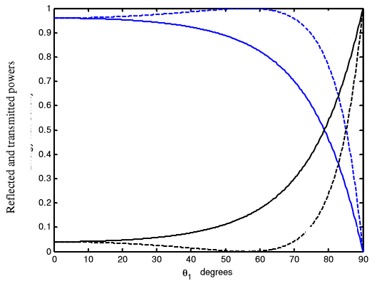
Notice that at grazing incidence we have total external reflection.
Black curves are the reflection coefficients of the reflected waves.
Blue curves are the transmission coefficients of the transmitted waves.
Continuous curves are for senkrecht (perpendicular) waves.
Dashed curves are for parallel waves.
At the Brewster angle no parallel waves are reflected.
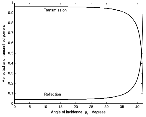
For light going from n_{1}\ =\ 1.5 to n_{2}\ =\ 1:
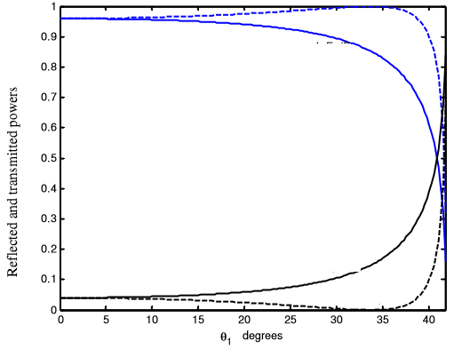
Black curves are the reflection coefficients of the reflected waves.
Blue curves are the transmission coefficients of the transmitted waves.
Continuous curves are for senkrecht (perpendicular) waves.
Dashed curves are for parallel waves.
For angles of incidence greater than 42 degrees (the critical angle for total internal reflection) all light is reflected. The phase of this totally reflected light is something that we have not yet discussed.
I return now to external reflection and to the graphs, repeated below, which show the reflected and transmitted amplitudes of the parallel and senkrecht components. The blue curves show the transmitted amplitudes, and there is no problem with them. The amplitudes are all positive, meaning that the transmitted waves have no phase change at the boundary. My students pointed out an apparent paradox with the dashed black curve, which is the reflected amplitude of the parallel component. It is positive, indicating (apparently) no phase change, even at normal incidence - and yet we know that there must be a phase change for reflected light at normal incidence. My students demanded (and rightly so) an explanation. The apparent anomaly was also noted on p.15. Following the diagram is the solution that I offer.
.PNG?revision=1&size=bestfit&width=500&height=397)
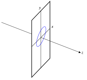
When we describe the state of polarization of light, whether, linear, circular or elliptical, we refer for convenience and of necessity to a coordinate system in which the z-axis is in the direction of the ray, and the xy-plane is perpendicular to it. The observer is supposed to be on the positive z-axis looking towards the source of light:
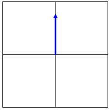
Consider a ray coming down at a steep angle to a water surface. Suppose at some instant of time the electric vector just above the surface is as shown by the little blue arrow below.
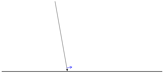
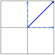
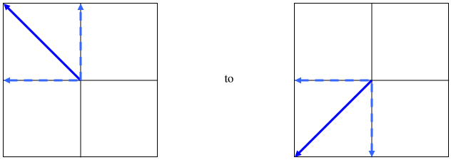
What does our observer (who is underneath the water) see, and how does he describe the state of polarization? This is what he sees:
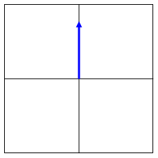
Now the light is reflected, the observer changes his position, and he looks down on the water from above.
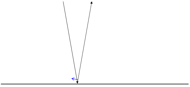
And this is what he sees:
And so there has been no phase change.
Or has there?
One might say that there has been a phase change, but it looks as though there hasn’t been. In effect, before and after, we are referring the situation to two reference frames, one of which is the mirror image of the other.
You will see that this apparent paradox does not arise with the senkrecht component.
We have hitherto considered the reflection and transmission of light that was initially plane polarized either parallel to the plane of incidence, or perpendicular (senkrecht) to it. Suppose that the incident light is plane polarized in a direction 45º to the parallel and senkrecht planes. We can resolve it into parallel and senkrecht components, each of amplitude \dfrac{E}{\sqrt{2}}. We suppose that the angle of incidence is \theta_{1}, and the angle of refraction, which is easily calculated from Snell’s Law, is \theta_{2}. And so there has been no phase change.
After reflection, the amplitudes of the parallel component will be \dfrac{E}{\sqrt{2}}\ \times\ \dfrac{\tan(\theta_{1}-\theta_{2})}{\tan(\theta_{1}+\theta_{2})}.
and the amplitude of the senkrecht component will be -\dfrac{E}{\sqrt{2}}\ \times\ \dfrac{\sin(\theta_{1}-\theta_{2})}{\sin(\theta_{1}+\theta_{2})}.
From these we can calculate the resultant amplitude of the reflected wave as well as its polarization direction (which is quite different from the plane of polarization of the incident wave.)
The transmitted light will have a parallel component of amplitude
\dfrac{E}{\sqrt{2}}\ \times\ \dfrac{2\sin\theta_{2}\cos\theta_{1}}{\sin(\theta_{1}\ +\ \theta_{2})\cos(\theta_{1}-\theta_{2})}
and a senkrecht component of amplitude
\dfrac{E}{\sqrt{2}}\ \times\ \dfrac{2}{1\ +\ \dfrac{\tan\theta_{1}}{\tan\theta_{2}}}.
From these we can calculate the resultant amplitude of the transmitted wave as well as its polarization direction (which, as for the reflected wave, is in a different plane from the plane of polarization of the incident wave.)
We show here the magnitudes (without regard to sign) of the amplitude reflection and transmission coefficients, and the polarization directions for the reflected and transmitted wave, as a function of angle of incidence \theta_{1}, assuming n\ =\ \frac{n_{2}}{n_{1}}\ =1.5.
At grazing incidence \theta_{1} = 90º, all the light is reflected. Although it has no particular significance, we note that, for n = 1.5, the reflection and transmission amplitude coefficients are equal (to 0.4544) for an angle of incidence equal to 72º.464. Except for normal and grazing incidence, the reflection and transmission amplitude coefficients do not add exactly to one. While there is a requirement for energy to be conserved, there is no similar requirement for the amplitudes.
As the angle of incidence goes from zero (normal incidence) to 90º (grazing incidence), the plane of polarization of the reflected wave goes from
Note that, for normal incidence, the reflected wave has a phase change for the senkrecht component, but (apparently) not for the parallel component, as explained above.
The plane of polarization of the transmitted moves slightly from the initial 45º to 56º.6 (the Brewster angle) at grazing incidence, although this has little significance since no light is transmitted at grazing incidence.
As described on \ref{eq:2.17}- \ref{eq:2.18}, if the incident, reflected and transmitted amplitudes are in the ratio , and the corresponding powers are in the ratio , then
P\ \ :\ \ P_{1} \ \ :\ \ P_{2}=1 \ \ :\ \ \left(\dfrac{E_{1}}{E}\right)^{2} \ \ :\ \ n\left(\dfrac{E_{2}}{E}\right)^{2}\dfrac{\cos\theta_{2}}{\cos\theta_{1}}
These are shown below for n = 1.5.
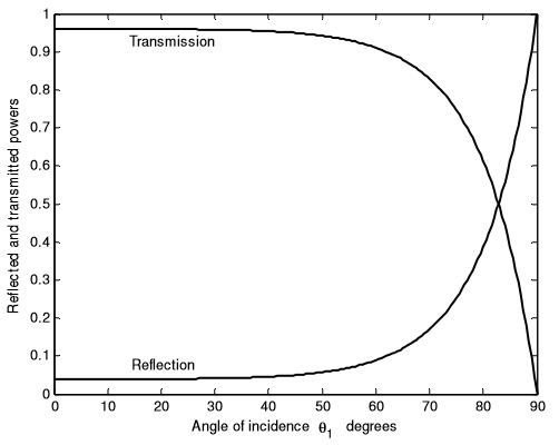
Recall that in these calculations, it has been assumed that the incident light is plane polarized at 45º to the parallel and senkrecht planes, so that the parallel and senkrecht amplitude components of the incident light are equal. Completely unpolarized incident light also has equal parallel and senkrecht amplitude components, so that the above graph also shows the reflection and transmission coefficients for unpolarized incident light. For n = 1.5, the reflection and transmission coefficients are equal for an angle of incidence of 82º.82. For any angle of incidence less than 60º, very much more light is transmitted than reflected., but, in the limit as \theta_{1}\rightarrow90^{\circ}, all the light is reflected.
We show below the reflection and transmission coefficients of internal reflection for angles of incidence from zero to the critical angle, which, for n = 1.5, is 41º.8. This is achieved merely by replacing 1.5 with \frac{2}{3} in the calculations.