
The Axis of Rotation for Rolling Motion
- Page ID
- 4125

\( \newcommand{\vecs}[1]{\overset { \scriptstyle \rightharpoonup} {\mathbf{#1}} } \)
\( \newcommand{\vecd}[1]{\overset{-\!-\!\rightharpoonup}{\vphantom{a}\smash {#1}}} \)
\( \newcommand{\dsum}{\displaystyle\sum\limits} \)
\( \newcommand{\dint}{\displaystyle\int\limits} \)
\( \newcommand{\dlim}{\displaystyle\lim\limits} \)
\( \newcommand{\id}{\mathrm{id}}\) \( \newcommand{\Span}{\mathrm{span}}\)
( \newcommand{\kernel}{\mathrm{null}\,}\) \( \newcommand{\range}{\mathrm{range}\,}\)
\( \newcommand{\RealPart}{\mathrm{Re}}\) \( \newcommand{\ImaginaryPart}{\mathrm{Im}}\)
\( \newcommand{\Argument}{\mathrm{Arg}}\) \( \newcommand{\norm}[1]{\| #1 \|}\)
\( \newcommand{\inner}[2]{\langle #1, #2 \rangle}\)
\( \newcommand{\Span}{\mathrm{span}}\)
\( \newcommand{\id}{\mathrm{id}}\)
\( \newcommand{\Span}{\mathrm{span}}\)
\( \newcommand{\kernel}{\mathrm{null}\,}\)
\( \newcommand{\range}{\mathrm{range}\,}\)
\( \newcommand{\RealPart}{\mathrm{Re}}\)
\( \newcommand{\ImaginaryPart}{\mathrm{Im}}\)
\( \newcommand{\Argument}{\mathrm{Arg}}\)
\( \newcommand{\norm}[1]{\| #1 \|}\)
\( \newcommand{\inner}[2]{\langle #1, #2 \rangle}\)
\( \newcommand{\Span}{\mathrm{span}}\) \( \newcommand{\AA}{\unicode[.8,0]{x212B}}\)
\( \newcommand{\vectorA}[1]{\vec{#1}} % arrow\)
\( \newcommand{\vectorAt}[1]{\vec{\text{#1}}} % arrow\)
\( \newcommand{\vectorB}[1]{\overset { \scriptstyle \rightharpoonup} {\mathbf{#1}} } \)
\( \newcommand{\vectorC}[1]{\textbf{#1}} \)
\( \newcommand{\vectorD}[1]{\overrightarrow{#1}} \)
\( \newcommand{\vectorDt}[1]{\overrightarrow{\text{#1}}} \)
\( \newcommand{\vectE}[1]{\overset{-\!-\!\rightharpoonup}{\vphantom{a}\smash{\mathbf {#1}}}} \)
\( \newcommand{\vecs}[1]{\overset { \scriptstyle \rightharpoonup} {\mathbf{#1}} } \)
\(\newcommand{\longvect}{\overrightarrow}\)
\( \newcommand{\vecd}[1]{\overset{-\!-\!\rightharpoonup}{\vphantom{a}\smash {#1}}} \)
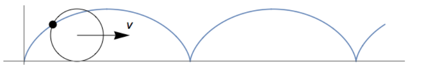
\(\newcommand{\avec}{\mathbf a}\) \(\newcommand{\bvec}{\mathbf b}\) \(\newcommand{\cvec}{\mathbf c}\) \(\newcommand{\dvec}{\mathbf d}\) \(\newcommand{\dtil}{\widetilde{\mathbf d}}\) \(\newcommand{\evec}{\mathbf e}\) \(\newcommand{\fvec}{\mathbf f}\) \(\newcommand{\nvec}{\mathbf n}\) \(\newcommand{\pvec}{\mathbf p}\) \(\newcommand{\qvec}{\mathbf q}\) \(\newcommand{\svec}{\mathbf s}\) \(\newcommand{\tvec}{\mathbf t}\) \(\newcommand{\uvec}{\mathbf u}\) \(\newcommand{\vvec}{\mathbf v}\) \(\newcommand{\wvec}{\mathbf w}\) \(\newcommand{\xvec}{\mathbf x}\) \(\newcommand{\yvec}{\mathbf y}\) \(\newcommand{\zvec}{\mathbf z}\) \(\newcommand{\rvec}{\mathbf r}\) \(\newcommand{\mvec}{\mathbf m}\) \(\newcommand{\zerovec}{\mathbf 0}\) \(\newcommand{\onevec}{\mathbf 1}\) \(\newcommand{\real}{\mathbb R}\) \(\newcommand{\twovec}[2]{\left[\begin{array}{r}#1 \\ #2 \end{array}\right]}\) \(\newcommand{\ctwovec}[2]{\left[\begin{array}{c}#1 \\ #2 \end{array}\right]}\) \(\newcommand{\threevec}[3]{\left[\begin{array}{r}#1 \\ #2 \\ #3 \end{array}\right]}\) \(\newcommand{\cthreevec}[3]{\left[\begin{array}{c}#1 \\ #2 \\ #3 \end{array}\right]}\) \(\newcommand{\fourvec}[4]{\left[\begin{array}{r}#1 \\ #2 \\ #3 \\ #4 \end{array}\right]}\) \(\newcommand{\cfourvec}[4]{\left[\begin{array}{c}#1 \\ #2 \\ #3 \\ #4 \end{array}\right]}\) \(\newcommand{\fivevec}[5]{\left[\begin{array}{r}#1 \\ #2 \\ #3 \\ #4 \\ #5 \\ \end{array}\right]}\) \(\newcommand{\cfivevec}[5]{\left[\begin{array}{c}#1 \\ #2 \\ #3 \\ #4 \\ #5 \\ \end{array}\right]}\) \(\newcommand{\mattwo}[4]{\left[\begin{array}{rr}#1 \amp #2 \\ #3 \amp #4 \\ \end{array}\right]}\) \(\newcommand{\laspan}[1]{\text{Span}\{#1\}}\) \(\newcommand{\bcal}{\cal B}\) \(\newcommand{\ccal}{\cal C}\) \(\newcommand{\scal}{\cal S}\) \(\newcommand{\wcal}{\cal W}\) \(\newcommand{\ecal}{\cal E}\) \(\newcommand{\coords}[2]{\left\{#1\right\}_{#2}}\) \(\newcommand{\gray}[1]{\color{gray}{#1}}\) \(\newcommand{\lgray}[1]{\color{lightgray}{#1}}\) \(\newcommand{\rank}{\operatorname{rank}}\) \(\newcommand{\row}{\text{Row}}\) \(\newcommand{\col}{\text{Col}}\) \(\renewcommand{\row}{\text{Row}}\) \(\newcommand{\nul}{\text{Nul}}\) \(\newcommand{\var}{\text{Var}}\) \(\newcommand{\corr}{\text{corr}}\) \(\newcommand{\len}[1]{\left|#1\right|}\) \(\newcommand{\bbar}{\overline{\bvec}}\) \(\newcommand{\bhat}{\widehat{\bvec}}\) \(\newcommand{\bperp}{\bvec^\perp}\) \(\newcommand{\xhat}{\widehat{\xvec}}\) \(\newcommand{\vhat}{\widehat{\vvec}}\) \(\newcommand{\uhat}{\widehat{\uvec}}\) \(\newcommand{\what}{\widehat{\wvec}}\) \(\newcommand{\Sighat}{\widehat{\Sigma}}\) \(\newcommand{\lt}{<}\) \(\newcommand{\gt}{>}\) \(\newcommand{\amp}{&}\) \(\definecolor{fillinmathshade}{gray}{0.9}\)When discussing the physics of a rolling wheel in an introductory course, it is always fun to point out that a point on the rim of the wheel traces out a cycloid, as shown in Figure \(\PageIndex{1}\).
When analyzing, for example, the kinetic energy \(K\) of the wheel, it is common to write to the total kinetic energy, \(K_{tot}\), as the sum of the translational kinetic energy of the center of mass of the wheel, \(K_{cm}\), and the kinetic energy of the rotation of the wheel about its center of mass, \(K_{rot}\):
\[K_{tot} = K_{cm} + K_{rot} \label{1}\]
Equation \ref{1} is often called Chasles’ theorem of 1830, although Mozzi is credited with an earlier result that is similar. For a wheel of mass \(m\) and radius \(R\) whose center of mass is moving to the right with a speed \(v\), the angular velocity is \(ω = v / R\). Then:
\[\begin{align} K_{cm} &= \frac{1}{ 2} mv^2 \\[4pt] K_{rot} &= \frac{1}{ 2} I ω^2 \label{2} \end{align} \]
where I is the moment of inertia of the wheel about its center of mass. Here we argue that this approach is very misleading for many students.
The problem with this conventional approach is that at every instant the wheel is not rotating about its center of mass: it is rotating about its contact point with the surface with angular velocity \(ω\). Thinking about the rotation being about the contact point makes it easy to see that the speed of the point on the top of the wheel is \(2v\) and the point in contact with the surface is momentarily at rest. It also shows that the velocity of the point on the outer edge of the flange of a railroad wheel will be negative when it is directly below the pivot point. Introducing cycloid motion as in Figure \(\PageIndex{1}\) helps some students to this angular velocity of the wheel rotating about its center of mass has the same value as the angular velocity of the wheel rotating about its contact point.
However, there is an issue with our perceptions and cycloid motion. If one views a film or animation of a point on the rim of a rolling object in a reference frame where the object is moving with speed v, Hume and Ivey pointed out long ago that we naturally try to view the situation where the motion of the point is simplest, which is the reference frame moving with the object in which case the motion of the point is just a circle. Put another way, we unconsciously do a mental change of reference frame to one where we “see” rolling motion as a combination of translational motion of the center of mass and rotational motion about its center of mass.
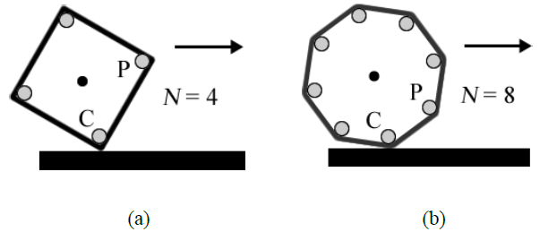
Because of this and perhaps other reasons, some students continue to struggle with the idea that the wheel is rotating about its contact point with the surface. Figure \(\PageIndex{2}\) sometimes helps with this. In Figure \(\PageIndex{2a}\), a square with \(N = 4\) sides is “rolling” on a surface without slipping. The corner C where the square is in contact with the surface is obviously stationary. The entire square is rotating about C until corner P reaches the surface. At that time corner P becomes stationary and corner C has an instantaneous upwards acceleration. Figure \(\PageIndex{2}\)(b) shows that the same situation is true for an octagon with N = 8 sides. When we let N →\(\infty\) the polygon becomes a circle but the same reasoning applies.
The difference between viewing the rotation about the center of mass and about the contact point can be illustrated with an activity that we have been using with our students for some years. We give them a toy yo-yo. Then we ask three questions, for each of which they have to answer the question first and then check their answer with the yo-yo. In Toronto, the students work on the questions in teams of 4.
Question \(\PageIndex{1}\)
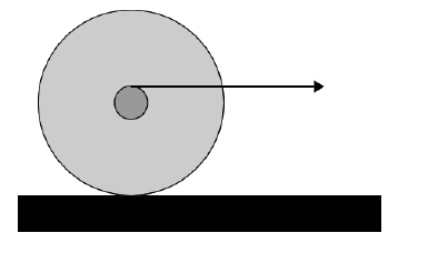
A yo-yo sits on the tabletop, and is gently pulled to the right by the horizontal string, which is wound about the axle as shown in the cross-section view. The pull is gentle enough that the yo-yo does not slip. Predict the motion of the yo-yo. Using the supplied yo-yo, check your prediction. If your prediction was wrong, explain where you went wrong.
Question \(\PageIndex{2}\)
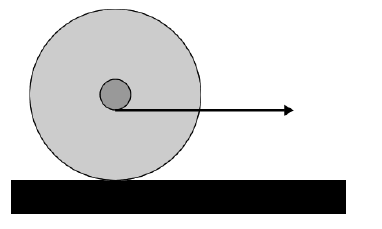
Now the yo-yo has the string wound around the axle as shown. The string is in contact with the bottom of the axle. If you gently pull the string to the right, predict the motion of the yo-yo. Check your prediction using the supplied yo-yo. If your prediction was wrong, explain where you went wrong.
Question \(\PageIndex{3}\)
Suppose that in the arrangement of Question \(\PageIndex{2}\), the string is not horizontal, but instead pulls the yo-yo to the right and slightly upwards. As the angle of the string with the horizontal is increased, predict what will happen. Test your prediction. Can you explain?
Most students will predict that for Question \(\PageIndex{1}\) the yo-yo will roll to the right, which is, of course, correct. However, many students will have a lot of trouble with Question \(\PageIndex{2}\) and will predict incorrectly that the yo-yo will roll to the left: it actually moves to the right too. Question \(\PageIndex{3}\) just confuses them more.
Conversations with the students indicate that many of them are thinking about the rotation of the wheel occurring about its center of mass, so in Question \(\PageIndex{2}\) the torque exerted by the string it in the opposite direction to the one in Question \(\PageIndex{1}\), and they think that the yo-yo will go to the left. The standard approach to the topic of rolling motion, such as Equation 1, only reinforces this misleading this idea.
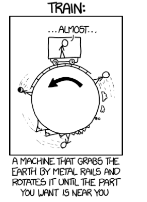
Sometimes the students will try to simultaneously think about the situation both in the lab frame where the yo-yo is moving with speed v and in a frame moving to the right with speed \(v\) where the yo-yo is only rotating, which only adds to the confusion. In this context we like to show the xkcd cartoon in Figure \(\PageIndex{3}\) to the students.
Getting the students to think about the rotation as instantaneously occurring about the contact point between the rim of the yo-yo and the tabletop allows them to eventually be led to an understanding that in both Questions \(\PageIndex{1}\) and \(\PageIndex{2}\) the direction of the torque exerted by the string is the same, will cause the yo-yo to try to spin in a clockwise direction about the contact point, which in turn causes the yo-yo to move to the right.
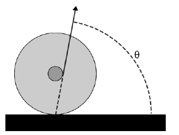
Once the students are comfortable with this way of thinking about rolling objects, then it is not too hard to lead them to the realization that for Question \(\PageIndex{3}\) the angle of the string for which there is no torque is as illustrated in Figure \(\PageIndex{3}\): the line of the string extended down goes exactly through the pivot point. Only angles greater than that shown in the figure will cause the yo-yo to move to the left. Pulling the string exactly in the direction of Figure \(\PageIndex{4}\) and giving the yo-yo a small horizontal push will cause it to oscillate back and forth about its equilibrium position.
One may later check student understanding by considering the string in contact with the top of the axle, as in Question \(\PageIndex{1}\), and on a test asking about the angle that will not cause the yo-yo to move either right or left.
Analyzing, say, the kinetic energy of a wheel that is instantaneously rotating about its contact point with the surface requires using the moment of inertia IC about that point. Then:
\[K = \frac{1}{ 2} I_Cω^2\label{3}\]
But there is a price to be paid: we must use the parallel-axis theorem to evaluate IC. If I is the moment of inertia about the center of mass of the yo-yo that theorem states:
\[I_C = I + mR^2\label{4}\]
so:
\[\begin{align} K &= \frac{1}{2} (I + mR^2 )ω^2 \\[4pt] &= \frac{1}{2} Iω^2 + \frac{1}{2} mR^2ω^2 \\[4pt] &= \frac{1}{2} Iω^2 + \frac{1}{2} mv^2 \label{5} \end{align}\]
This duplicates Equations \ref{1} and \ref{2}, but the conceptual basis of Equation \ref{5} is very different.
We did an informal “literature search” of the 19 introductory physics textbooks on our bookshelf that discuss rotation of rigid bodies. Surprisingly, only 8 of them actually covered rolling motion in any significant way and only 2 of those did it as we are advocating, 5 with the other 6 only using the conventional but misleading view that rolling motion is a combination of translational and rotational motions. None of the 8 textbooks that we looked at that discuss rolling motion make any reference to torques exerted on a wheel that is rolling horizontally and being pulled, and we seldom discuss this with our students beyond the qualitative arguments given above. For introductory students, we actively avoid doing the full dynamics using F = ma and \(τ_{net}\) = IP \(\alpha \), where IP is the moment inertia of the yo-yo about the point that is used for evaluating the net torque and α is the angular acceleration. The appendix discusses this further.
Finally, rotation of rigid bodies is always a difficult topic for beginning students. Considering the subtleties discussed here, perhaps the majority of the textbooks that we looked at that do rotations of rigid bodies but omit the topic of rolling motion made a wise pedagogical choice. If the textbook approaches rolling motion the way we are advocating, such as Refs. 5, then the yo-yo activities that we use with our students are educational and fun. If a teacher wishes to discuss rolling motion in their course and their textbook uses the conventional view of Equation 1, then a difficult question is whether to do the topic right and diverge from the textbook, to stick to the textbook and mislead the students, or perhaps re-consider and drop rolling motion from the syllabus.
APPENDIX
We know that when doing the dynamics of a rotating body that has a net torque acting on it, the analysis must be done about the actual axis of rotation. One reason for this is that if we analyze the dynamics about any other point, that point is in general accelerating so the analysis is being done in a non-inertial frame of reference. We can also see that using the wrong axis of rotation gives incorrect results by analyzing the pulley of an Atwood machine with moment inertia about its axle I, radius R, and mass m, as in Figure A1.
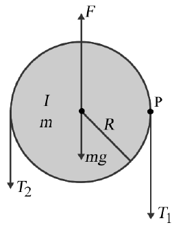
The total force acting on the pulley is zero so:
\[F = mg + T_1 + T_2 \label{A1}\]
Analyzing the torque and angular acceleration about the actual axis of rotation, the axle of the pulley, gives:
\[τ_{net} = T_1R − T_2R = Iα \label{A2}\]
If we analyze about point \(P\), the right edge of the pulley where \(T_1\) is applied, we get:
\[τ_{net} = (F − mg)R − T_2 × 2R = (I + mR^2 )α ~~~~~~~~~~WRONG \label{A3}\]
Using Equation \ref{A1} to eliminate \(F - mg\) from Equation \ref{A3} gives:
\[τ_{net} = T_1R − T_2R = (I + mR^2 )α ~~~~~~~~~~WRONG \label{A4}\]
The net torque in Equations \ref{A2} and \ref{A4} is the same, but the moments of inertia are different so the angular accelerations are also different. Note that if we think of point P as attached to the right-hand string, if T1 ≠ T2 then it is accelerating.
For a pulled yo-yo, consider the string in contact with the top of the axle of the yo-yo with r the radius of the axle, and assume that the static frictional force, fs, points to the left as in Figure A2. Not considered are the force due to gravity or the normal force by the surface on the yo-yo: these are equal and opposite, have no horizontal components, and do not cause a torque about either the center of mass or the contact point with the surface.
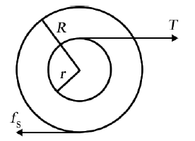
The dynamics equation for translational motion is:
\[F_{net} = T − f_s = ma = mRα \label{A5}\]
If we evaluate the torques about the center of mass the rotational dynamics equation is:
\[τ_{net} = Tr + f_sR = Iα \label{A6}\]
Equations \ref{A5} – \ref{A6} can only be solved for the angular acceleration only by eliminating either fs or \(T\). Eliminating \(f_s\) gives:
\[α = \frac{T (R + r) }{I + mR^2} \label{A7}\]
The rotational dynamics equation evaluated about the contact point is:
\[τ_{net} = T (R + r) = (I + mR^2 )α \label{A8}\]
Just by inspection we see that \(α\) in Equation \ref{A8} is the same as the solution Equation \ref{A7}. This is surprising.
Some insight can be gained by eliminating \(α\) from Equations \ref{A5} and \ref{A6}, or from Equations \ref{A5} and \ref{A8}, and solving for fs.
\[f_s = \frac{T (I − mRr)}{ I + mR^2} \label{A9}\]
We see that the frictional force depends on \(T\). It is not clear to us why this coupling of \(f_s\) and \(T\) means that the results of the analysis are independent of the assumed axis of rotation, or perhaps it is due to some other cause. We can also see from Equation \ref{A9} that for some geometries \(f_s < 0\), i.e. the frictional force points to the right.
The situation is similar when we analyze the case of the string in contact with the bottom of the axle. Although the expressions, which are not shown, are different from Equations \ref{A6} – \ref{A9}, they too are independent of the assumed axis of rotation. However one result is:
\[α = \frac{T (R − r)}{ I + mR^2} \label{A10}\]
This is \(> 0\) for \(R > r\), which correctly indicates that the yo-yo rolls to the right. Also \(f_s\) depends on \(T\), with the same expression when evaluated about either axis of rotation. Also, if \(T\) is applied at the center of mass of the object \(r = 0\) and Equation \ref{A10} becomes identical to Equation \ref{A7}, as it should.
The mystery of why the dynamics of rolling motion is independent of the chosen axis of rotation deepens when we consider an object rolling down an inclined plane. Mazur, for example, analyzes the dynamics assuming that the rotation is about the center of mass. Analyzing this for the contact point as the axis of rotation gives the same results for the accelerations and the frictional force. Those results are also not shown, but are easily duplicated. Here too, however, the frictional force is coupled to the other force exerted on the system that can cause a torque, in this case \(mg\sin(\theta)\) .
A further subtlety in the analysis of rolling object regards the contact point of the object with the surface. In addition to just saying that point is stationary without further thought, there are at least two other ways to think about that point:
- It is moving to the right with speed \(v\), or
- It is attached to the point on the rim of the object, in which case it is instantaneously accelerating upwards.
However, Jensen has shown Equation \ref{A8} is correct for the first case if the rolling body is symmetric around its center of mass, and is correct for the second case if the acceleration of the point is parallel to the line connecting the center of mass to the contact point. Both of these conditions are true for the pulled yo-yo and for an object rolling down an inclined plane.
Note that for the Atwood machine there is also a coupling of the forces since \(F – mg = T_1 +T_2\), but for that case the solutions depend on the assumed axis of rotation, so there is some difference in the coupling for the Atwood machine and for the cases of rolling motion considered in this appendix.
Although we suspect that it is the nature of the coupling of the two forces for the pulled yo-yo or for an object rolling down an incline that makes the choice of assumed axis of rotation irrelevant, at least for this physics teacher it is far from clear why this is so. Therefore, we think doing the full dynamics of a pulled yo-yo is not appropriate for introductory students. The exception is those few students that are much smarter than their teacher. We are waiting for the next such student we encounter, and will try to entice him/her to think about these questions and teach us what is going on: as Wheeler said, “We all know that the real reason universities have students is to educate the professors.”
Acknowledgements
The issues discussed here have been clarified by discussions with colleagues Jason Harlow, Eli Honig, and Brian Wilson. Figure \(\PageIndex{2}\) is based on an idea by colleague Stephen Foster.