
2.8.1: Snells law and refraction
- Page ID
- 138911
\( \newcommand{\vecs}[1]{\overset { \scriptstyle \rightharpoonup} {\mathbf{#1}} } \)
\( \newcommand{\vecd}[1]{\overset{-\!-\!\rightharpoonup}{\vphantom{a}\smash {#1}}} \)
\( \newcommand{\dsum}{\displaystyle\sum\limits} \)
\( \newcommand{\dint}{\displaystyle\int\limits} \)
\( \newcommand{\dlim}{\displaystyle\lim\limits} \)
\( \newcommand{\id}{\mathrm{id}}\) \( \newcommand{\Span}{\mathrm{span}}\)
( \newcommand{\kernel}{\mathrm{null}\,}\) \( \newcommand{\range}{\mathrm{range}\,}\)
\( \newcommand{\RealPart}{\mathrm{Re}}\) \( \newcommand{\ImaginaryPart}{\mathrm{Im}}\)
\( \newcommand{\Argument}{\mathrm{Arg}}\) \( \newcommand{\norm}[1]{\| #1 \|}\)
\( \newcommand{\inner}[2]{\langle #1, #2 \rangle}\)
\( \newcommand{\Span}{\mathrm{span}}\)
\( \newcommand{\id}{\mathrm{id}}\)
\( \newcommand{\Span}{\mathrm{span}}\)
\( \newcommand{\kernel}{\mathrm{null}\,}\)
\( \newcommand{\range}{\mathrm{range}\,}\)
\( \newcommand{\RealPart}{\mathrm{Re}}\)
\( \newcommand{\ImaginaryPart}{\mathrm{Im}}\)
\( \newcommand{\Argument}{\mathrm{Arg}}\)
\( \newcommand{\norm}[1]{\| #1 \|}\)
\( \newcommand{\inner}[2]{\langle #1, #2 \rangle}\)
\( \newcommand{\Span}{\mathrm{span}}\) \( \newcommand{\AA}{\unicode[.8,0]{x212B}}\)
\( \newcommand{\vectorA}[1]{\vec{#1}} % arrow\)
\( \newcommand{\vectorAt}[1]{\vec{\text{#1}}} % arrow\)
\( \newcommand{\vectorB}[1]{\overset { \scriptstyle \rightharpoonup} {\mathbf{#1}} } \)
\( \newcommand{\vectorC}[1]{\textbf{#1}} \)
\( \newcommand{\vectorD}[1]{\overrightarrow{#1}} \)
\( \newcommand{\vectorDt}[1]{\overrightarrow{\text{#1}}} \)
\( \newcommand{\vectE}[1]{\overset{-\!-\!\rightharpoonup}{\vphantom{a}\smash{\mathbf {#1}}}} \)
\( \newcommand{\vecs}[1]{\overset { \scriptstyle \rightharpoonup} {\mathbf{#1}} } \)
\(\newcommand{\longvect}{\overrightarrow}\)
\( \newcommand{\vecd}[1]{\overset{-\!-\!\rightharpoonup}{\vphantom{a}\smash {#1}}} \)
\(\newcommand{\avec}{\mathbf a}\) \(\newcommand{\bvec}{\mathbf b}\) \(\newcommand{\cvec}{\mathbf c}\) \(\newcommand{\dvec}{\mathbf d}\) \(\newcommand{\dtil}{\widetilde{\mathbf d}}\) \(\newcommand{\evec}{\mathbf e}\) \(\newcommand{\fvec}{\mathbf f}\) \(\newcommand{\nvec}{\mathbf n}\) \(\newcommand{\pvec}{\mathbf p}\) \(\newcommand{\qvec}{\mathbf q}\) \(\newcommand{\svec}{\mathbf s}\) \(\newcommand{\tvec}{\mathbf t}\) \(\newcommand{\uvec}{\mathbf u}\) \(\newcommand{\vvec}{\mathbf v}\) \(\newcommand{\wvec}{\mathbf w}\) \(\newcommand{\xvec}{\mathbf x}\) \(\newcommand{\yvec}{\mathbf y}\) \(\newcommand{\zvec}{\mathbf z}\) \(\newcommand{\rvec}{\mathbf r}\) \(\newcommand{\mvec}{\mathbf m}\) \(\newcommand{\zerovec}{\mathbf 0}\) \(\newcommand{\onevec}{\mathbf 1}\) \(\newcommand{\real}{\mathbb R}\) \(\newcommand{\twovec}[2]{\left[\begin{array}{r}#1 \\ #2 \end{array}\right]}\) \(\newcommand{\ctwovec}[2]{\left[\begin{array}{c}#1 \\ #2 \end{array}\right]}\) \(\newcommand{\threevec}[3]{\left[\begin{array}{r}#1 \\ #2 \\ #3 \end{array}\right]}\) \(\newcommand{\cthreevec}[3]{\left[\begin{array}{c}#1 \\ #2 \\ #3 \end{array}\right]}\) \(\newcommand{\fourvec}[4]{\left[\begin{array}{r}#1 \\ #2 \\ #3 \\ #4 \end{array}\right]}\) \(\newcommand{\cfourvec}[4]{\left[\begin{array}{c}#1 \\ #2 \\ #3 \\ #4 \end{array}\right]}\) \(\newcommand{\fivevec}[5]{\left[\begin{array}{r}#1 \\ #2 \\ #3 \\ #4 \\ #5 \\ \end{array}\right]}\) \(\newcommand{\cfivevec}[5]{\left[\begin{array}{c}#1 \\ #2 \\ #3 \\ #4 \\ #5 \\ \end{array}\right]}\) \(\newcommand{\mattwo}[4]{\left[\begin{array}{rr}#1 \amp #2 \\ #3 \amp #4 \\ \end{array}\right]}\) \(\newcommand{\laspan}[1]{\text{Span}\{#1\}}\) \(\newcommand{\bcal}{\cal B}\) \(\newcommand{\ccal}{\cal C}\) \(\newcommand{\scal}{\cal S}\) \(\newcommand{\wcal}{\cal W}\) \(\newcommand{\ecal}{\cal E}\) \(\newcommand{\coords}[2]{\left\{#1\right\}_{#2}}\) \(\newcommand{\gray}[1]{\color{gray}{#1}}\) \(\newcommand{\lgray}[1]{\color{lightgray}{#1}}\) \(\newcommand{\rank}{\operatorname{rank}}\) \(\newcommand{\row}{\text{Row}}\) \(\newcommand{\col}{\text{Col}}\) \(\renewcommand{\row}{\text{Row}}\) \(\newcommand{\nul}{\text{Nul}}\) \(\newcommand{\var}{\text{Var}}\) \(\newcommand{\corr}{\text{corr}}\) \(\newcommand{\len}[1]{\left|#1\right|}\) \(\newcommand{\bbar}{\overline{\bvec}}\) \(\newcommand{\bhat}{\widehat{\bvec}}\) \(\newcommand{\bperp}{\bvec^\perp}\) \(\newcommand{\xhat}{\widehat{\xvec}}\) \(\newcommand{\vhat}{\widehat{\vvec}}\) \(\newcommand{\uhat}{\widehat{\uvec}}\) \(\newcommand{\what}{\widehat{\wvec}}\) \(\newcommand{\Sighat}{\widehat{\Sigma}}\) \(\newcommand{\lt}{<}\) \(\newcommand{\gt}{>}\) \(\newcommand{\amp}{&}\) \(\definecolor{fillinmathshade}{gray}{0.9}\)|
Snell's laws quantifies refraction between two media. Here we use animations to illustrate and to derive Snell's law, then show an experiment to test the law and to measure the refractive index of glass. This page supports the multimedia tutorial Geometrical Optics. |
 |
Refraction at a plane interface
In this animation, a vertical line separates medium 1 on the left and medium 2 on the right. The grey lines are rays showing refraction at the interface. The red lines represent 'crests' of the waves: points on these lines all have maximum value of the electric field. The histogram shows the electric field at the position indicated by the dot. First, let's note that, at a point on the interface, such as the red dot, the number of wave crests that arrive from the left in a second equals the number that leave to the right. So the frequency is the same in the two media. In Travelling waves, we related wavelength λ to the frequency f and c, the wave speed: λ = c/f. So, with frequency the same in both media, the wavelength is shorter in medium 2, which has the slower wave speed, as shown in the animation. We shall now relate the wave speeds to the angles of incidence and refraction. |
||||
Snell's law: derivation
Two right-angle triangles at the interace, sharing the hypotenuse d, allow us to relate the wavelengths, λ1 and λ2, to the angles of incidence θ1 and refraction θ2. The refractive index n1 for a medium is defined as the ratio of the speed of light c in vacuum to that in the medium, c1. Because the frequency is the same in the two media, the ratio of wavelengths equals that of speeds, so we have:
|
||||
Snell's law: experimental determination of the refactive indexThis experiment uses a narrow beam of light passing from air into glass and then to air. The experiment is practically easier using a hemicylindrical prism of glass, with the beam entering from the curved side and travelling along a radius. Thus, at the air-glass interface, the angles of incidence and refraction are both zero. By rotating the hemicylinder about the centre of its curved surface, however, we vary the angle of incidence, and thus that of refraction. (The hemicylindrical is convenient, but not necessary for a home experiment: any prism of glass would do.)
For this experiment, we used six different angles of incidence. For the last few, we could distinguish clearly the angles of refraction for blue and red, so they are shown separately in the table and on the graph. To the precision of the measurements (indicated by the error bars), sin θair/sin θglass is a constant, which is nglass/nair. Because nair is approximately 1, the slope gives the value of nglass, which is 1.52 ± 0.02 for this sample of glass.
|
||||
Refaction: some examplesThe two examples we show below use rotational symmetry. So let's see how light would be refracted through a cylinder having higher refractive index. The dashed liones are radii and so are normal to the surface
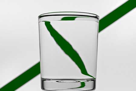
Now look at the photo at right (click on it for a larger version): there are three images of the opera house in this tulip-shaped wine glass. In all cases, the lens has rotational symmetry about a vertical axis so, as in the previous case, all three images are inverted left to right. First, let's look at the top image. This is produced in a region of the glass which is convex left to right but concave top to bottom. So the image is inverted left to right, but not in the vertical direction. Second, we look at the image below, in the bulbous part of the glass. In this region, the glass is convex in both the vertical and horizontal directions, so the image is inverted left to right and also top to bottom. Finally, there is a tiny image in the top of the stem of the glass. Here the glass is convex left to right, but concave in the vertical direction, so the image is inverted left to right but is not inverted in the vertical direction. |
Links and further information
- Chromatic dispersion, rainbows and Alexander's dark band
- Dispersion and chromatic aberration
- Lenses and images
- Microscopes and magnifiers
- Mirages and the Green Flash
- Newton's prisms
- Optical fibres and cladding
- Reflecting Newtonian telescope
- Refracting telescope
- Total internal reflection
- The multimedia tutorial Geometrical Optics also has a longer list of support pages
Snell's Law, also known as the Law of Refraction, is an equation that relates the angle of the incident light and the angle of the transmitted light at the interface of two different mediums. Snell's Law can be applied to all materials, in all phases of matter. Most people are familiar with Snell's Law because of the apparent shortening of their legs that is observed when standing in water. Another commonly recognized example of refraction in a material is diamonds. The many facets of the cut diamond combined with a high index of refraction give diamonds the brilliance that they are known for. Snell's Law is especially important for optical devices, such as fiber optics. Snell's Law states that the ratio of the sine of the angles of incidence and transmission is equal to the ratio of the refractive index of the materials at the interface.
Speed of Light and Index of Refraction
Refraction occurs because the speed of the light changes when it passes into a new medium. The speed of light in a medium is given by the following equation:
\[c=nv\]
where n is the refractive index of the material and c is the speed of light in a vacuum. The refractive index can also be determined from the permittivity and permeability of the material. Therefore it is possible to know the optical properties of the material from the electrical properties of the material. Using these properties, the index of refraction is given by the following equation:
\[n=\dfrac{c}{v}=\sqrt{\dfrac{\varepsilon \mu }{\varepsilon_{0} \mu_{0}}}=\sqrt{\varepsilon_{r} \mu_{r}}\]
where εr and μr are the permativity and permeability of the material respectively. Table 1 lists the index of refraction for some common materials.
| Vacuum | 1.000 |
| Air | 1.000293 |
| Water | 1.333 |
| Ice | 1.309 |
| Plexiglass | 1.49 |
| Soda-Lime Glass | 1.46 |
| Diamond | 2.42 |
Snell's Law
Snell's law relates the sines of the angles of incidence and transmission to the index of refraction for each material:
\[\dfrac{\sin \theta_{1}}{\sin \theta_{2}}=\dfrac{n_{2}}{n_{1}}\]
It should be noted that the angles are measured from the normal line at the interface (Figure 1).
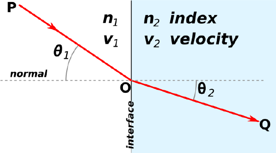 Figure \(\PageIndex{1}\): Refraction at the interface between two materials (Wikipedia)
Additionally, because the index of refraction is related to the speed of light in the material, the following equation is also true:
\[\dfrac{\sin \theta_{1}}{sin \theta_{2}}=\dfrac{v_{1}}{v_{2}}\]
As light crosses the boundary between two different materials, the light will be refracted either at a greater angle or a smaller angle depending on the relative refractive indecies of each material. If the index of refraction for the second material is greater than the first material, then the light will be refracted to a smaller angle.
Theory: Light as a Wave
Snell's Law arises from the wave nature of light. Light can be described in one of several ways: a ray, a particle (photon), and as a wave. The interaction of light with a material can be best described for light when light is thought of as a wave.
The key to understanding the behavior of light at an interface is that Energy must be conserved: the energy of light going in the first material must be the same as the energy of the light in the second material. The energy of light can be described in the following way:
\[E=hf=\dfrac{hv}{\lambda}\]
where f is the frequency of the wave, v is the speed of the wave, h is Plank's constant, and c is the speed of light in a vacuum.
Because energy must be conserved at the boundary, the frequency of the light must remain the same for all materials. This is because the number of waves arriving at the interface per unit time must be the same as the number of waves leaving the interface per unit time; the boundary interface cannot create or destroy waves. This concept is shown in Figure 2.
Figure 2: The number of wavefronts arriving at the interface must be the same at the number leaving the interface.
(taken with permission from Wikipedia)
However, the speed that a wave propagates at is dependent on the medium the light is traveling in. This velocity change is due to the interaction between light and the resonance of the electrons in the material which are either tightly or loosely held to the nuclei in the material. It is this change in velocity that causes the refraction of light in a new medium. The velocity of light in a medium is given by the following equation: \[v=\dfrac{1}{\sqrt{\varepsilon \mu }}\]where ε is the the permativity and μ is the permeability of the particular material.
Critical Angle and Total Internal Reflection
An important extension of Snell's law is the concept of Total Internal Reflection and the critical angle. For any combination of mediums, there is an angle for which the refracted light will be perpendicular to the normal (Figure 3). The critical angle is given by the equation:
\[\theta_{c}=\sin^{-1} \left [ \dfrac{n_{1}}{n_{2}} \right ]\]
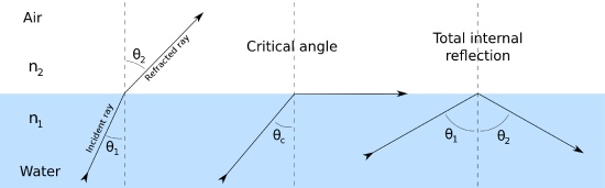 Figure 3: Refraction, Critical Angle, and Total Internal Reflection at an interface (taken with permission from Wikipedia)
If the incident angle is greater than the critical angle, the light will be completely reflected back into the original medium. This is shown in the last image of Figure 3. Total Internal Reflection can also occur if there is a significant difference in the refractive index between the two materials. It is this type of total internal reflection that gives rise to fiber optics.
Applications and Importance
A very important application of Snell's Law is Fiber Optics. Fiber Optics are used for many applications, from telecommunications to data transmission in high speed servers. Because the fibers are not laid out in straight lines, the light must be guided down the length of the fiber. This is achieved with one of three types of fiber: step-index fiber, graded-index fiber (multimode), or single-mode fiber. These fiber types are shown in Figure 4.
|
Figure 4: Schematics and comparison of Fiber Optic Cable types. |
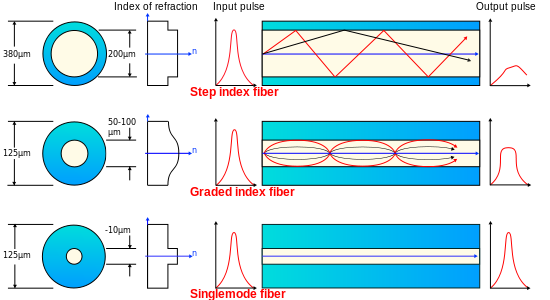
In step-index fibers, there is a very large decrease in the index of refraction at the interface between the glass fiber and its cladding. This causes the light to move in a zigzag pattern down the length of the fiber, and because of this there is a considerable distortion in the light pulse. It is because of this distortion that step-index fibers are only used for applications that have shorter fiber lengths.
For graded-mode fibers, the index of refraction of the core decreases mas the radius of the fiber gets larger. This is achieved by introducing additives to the fiber glass, such as B2O3 and GeO2. By having the index of refraction change gradually, the light is gradually bent back towards the center of the fiber. Therefore, the distortion of the light is much smaller than it is for the step-index fiber. This means that a longer fiber can be used if the fiber has graded-index core. Graded-index core fibers are generally used for data transfer, such as in local area networks.
The final type of fiber is the single-mode fiber. Single-mode fibers are generally used for long distance networks where there is very little need for a curve in the fiber. In single-mode fibers, the light travels straight down the axis of the fiber and does not experience refraction. This is shown in Figure 4.
Questions
- Calculation of Transmittance Angle
Using values given in Table 1, calculate the angle of transmittance if the incident angle of the light is 26o. The light is moving from air into glass. - Is Snell's Law only for solid materials?
- Which direction will light bend (towards or away from the normal) if the index of refraction for the second material in the interface is higher than the first? Why?
Answers
- θ=17.5
- No
- The transmitted angle will be smaller than the incident angle. So the light will bend towards the normal. This is because the a higher index of refraction in the second material causes a decrease in the speed of the light in the second material.
Additional Links
- Polarization of Waves (Chemwiki)
- Refractive Index (Wikipedia)
- Critical Angle (Wikipedia)
- Snell's Law (Wikipedia)
- Graded-Index Fiber (Wikipedia)
- Single-Mode Fiber (Wikipedia)
- Optical Fiber (Wikipedia)
- Fiber Optics (Chemwiki)
- Glass (Chemwiki)
- Material Science and Engineering: An Introduction (PDF)
- Permeability (Wikipedia)
- Permitivity (Wikipedia)
- Total Internal Reflection (Wikipedia)
- Reflection Conditions (Chemwiki)
References
- Flens, Frank. Director of Engineering, Finisar. Personal interview.
- Hummel, Rolf E. Electronic Properties of Materials. New York: Springer, 2011. Print.
- Young, Hugh D. , Roger A. Freedman. Sears and Zemansky's University Physics: with Modern Physics. San Fransisco: Pearson Addison Wesley, 2008. Print.
- Hecht, E., and A. Zajac. Optics. 1979. Print.
- Shackelford, James F. Introduction to Materials Science for Engineers. Upper Saddle River, NJ: Pearson/Prentice Hall, 2005. Print.
- Hecht, Eugene. Optics. Reading, MA: Addison-Weley, 2002. Print.
- Callister, William D., David G. Rethwisch. Materials Science and Engineering: An Introduction. December 2009. Print.
Contributors
- Hannah Flens (UC Davis, Material Science and Engineering)