
2.8.9: Mirrors and images
- Page ID
- 138919
\( \newcommand{\vecs}[1]{\overset { \scriptstyle \rightharpoonup} {\mathbf{#1}} } \)
\( \newcommand{\vecd}[1]{\overset{-\!-\!\rightharpoonup}{\vphantom{a}\smash {#1}}} \)
\( \newcommand{\dsum}{\displaystyle\sum\limits} \)
\( \newcommand{\dint}{\displaystyle\int\limits} \)
\( \newcommand{\dlim}{\displaystyle\lim\limits} \)
\( \newcommand{\id}{\mathrm{id}}\) \( \newcommand{\Span}{\mathrm{span}}\)
( \newcommand{\kernel}{\mathrm{null}\,}\) \( \newcommand{\range}{\mathrm{range}\,}\)
\( \newcommand{\RealPart}{\mathrm{Re}}\) \( \newcommand{\ImaginaryPart}{\mathrm{Im}}\)
\( \newcommand{\Argument}{\mathrm{Arg}}\) \( \newcommand{\norm}[1]{\| #1 \|}\)
\( \newcommand{\inner}[2]{\langle #1, #2 \rangle}\)
\( \newcommand{\Span}{\mathrm{span}}\)
\( \newcommand{\id}{\mathrm{id}}\)
\( \newcommand{\Span}{\mathrm{span}}\)
\( \newcommand{\kernel}{\mathrm{null}\,}\)
\( \newcommand{\range}{\mathrm{range}\,}\)
\( \newcommand{\RealPart}{\mathrm{Re}}\)
\( \newcommand{\ImaginaryPart}{\mathrm{Im}}\)
\( \newcommand{\Argument}{\mathrm{Arg}}\)
\( \newcommand{\norm}[1]{\| #1 \|}\)
\( \newcommand{\inner}[2]{\langle #1, #2 \rangle}\)
\( \newcommand{\Span}{\mathrm{span}}\) \( \newcommand{\AA}{\unicode[.8,0]{x212B}}\)
\( \newcommand{\vectorA}[1]{\vec{#1}} % arrow\)
\( \newcommand{\vectorAt}[1]{\vec{\text{#1}}} % arrow\)
\( \newcommand{\vectorB}[1]{\overset { \scriptstyle \rightharpoonup} {\mathbf{#1}} } \)
\( \newcommand{\vectorC}[1]{\textbf{#1}} \)
\( \newcommand{\vectorD}[1]{\overrightarrow{#1}} \)
\( \newcommand{\vectorDt}[1]{\overrightarrow{\text{#1}}} \)
\( \newcommand{\vectE}[1]{\overset{-\!-\!\rightharpoonup}{\vphantom{a}\smash{\mathbf {#1}}}} \)
\( \newcommand{\vecs}[1]{\overset { \scriptstyle \rightharpoonup} {\mathbf{#1}} } \)
\(\newcommand{\longvect}{\overrightarrow}\)
\( \newcommand{\vecd}[1]{\overset{-\!-\!\rightharpoonup}{\vphantom{a}\smash {#1}}} \)
\(\newcommand{\avec}{\mathbf a}\) \(\newcommand{\bvec}{\mathbf b}\) \(\newcommand{\cvec}{\mathbf c}\) \(\newcommand{\dvec}{\mathbf d}\) \(\newcommand{\dtil}{\widetilde{\mathbf d}}\) \(\newcommand{\evec}{\mathbf e}\) \(\newcommand{\fvec}{\mathbf f}\) \(\newcommand{\nvec}{\mathbf n}\) \(\newcommand{\pvec}{\mathbf p}\) \(\newcommand{\qvec}{\mathbf q}\) \(\newcommand{\svec}{\mathbf s}\) \(\newcommand{\tvec}{\mathbf t}\) \(\newcommand{\uvec}{\mathbf u}\) \(\newcommand{\vvec}{\mathbf v}\) \(\newcommand{\wvec}{\mathbf w}\) \(\newcommand{\xvec}{\mathbf x}\) \(\newcommand{\yvec}{\mathbf y}\) \(\newcommand{\zvec}{\mathbf z}\) \(\newcommand{\rvec}{\mathbf r}\) \(\newcommand{\mvec}{\mathbf m}\) \(\newcommand{\zerovec}{\mathbf 0}\) \(\newcommand{\onevec}{\mathbf 1}\) \(\newcommand{\real}{\mathbb R}\) \(\newcommand{\twovec}[2]{\left[\begin{array}{r}#1 \\ #2 \end{array}\right]}\) \(\newcommand{\ctwovec}[2]{\left[\begin{array}{c}#1 \\ #2 \end{array}\right]}\) \(\newcommand{\threevec}[3]{\left[\begin{array}{r}#1 \\ #2 \\ #3 \end{array}\right]}\) \(\newcommand{\cthreevec}[3]{\left[\begin{array}{c}#1 \\ #2 \\ #3 \end{array}\right]}\) \(\newcommand{\fourvec}[4]{\left[\begin{array}{r}#1 \\ #2 \\ #3 \\ #4 \end{array}\right]}\) \(\newcommand{\cfourvec}[4]{\left[\begin{array}{c}#1 \\ #2 \\ #3 \\ #4 \end{array}\right]}\) \(\newcommand{\fivevec}[5]{\left[\begin{array}{r}#1 \\ #2 \\ #3 \\ #4 \\ #5 \\ \end{array}\right]}\) \(\newcommand{\cfivevec}[5]{\left[\begin{array}{c}#1 \\ #2 \\ #3 \\ #4 \\ #5 \\ \end{array}\right]}\) \(\newcommand{\mattwo}[4]{\left[\begin{array}{rr}#1 \amp #2 \\ #3 \amp #4 \\ \end{array}\right]}\) \(\newcommand{\laspan}[1]{\text{Span}\{#1\}}\) \(\newcommand{\bcal}{\cal B}\) \(\newcommand{\ccal}{\cal C}\) \(\newcommand{\scal}{\cal S}\) \(\newcommand{\wcal}{\cal W}\) \(\newcommand{\ecal}{\cal E}\) \(\newcommand{\coords}[2]{\left\{#1\right\}_{#2}}\) \(\newcommand{\gray}[1]{\color{gray}{#1}}\) \(\newcommand{\lgray}[1]{\color{lightgray}{#1}}\) \(\newcommand{\rank}{\operatorname{rank}}\) \(\newcommand{\row}{\text{Row}}\) \(\newcommand{\col}{\text{Col}}\) \(\renewcommand{\row}{\text{Row}}\) \(\newcommand{\nul}{\text{Nul}}\) \(\newcommand{\var}{\text{Var}}\) \(\newcommand{\corr}{\text{corr}}\) \(\newcommand{\len}[1]{\left|#1\right|}\) \(\newcommand{\bbar}{\overline{\bvec}}\) \(\newcommand{\bhat}{\widehat{\bvec}}\) \(\newcommand{\bperp}{\bvec^\perp}\) \(\newcommand{\xhat}{\widehat{\xvec}}\) \(\newcommand{\vhat}{\widehat{\vvec}}\) \(\newcommand{\uhat}{\widehat{\uvec}}\) \(\newcommand{\what}{\widehat{\wvec}}\) \(\newcommand{\Sighat}{\widehat{\Sigma}}\) \(\newcommand{\lt}{<}\) \(\newcommand{\gt}{>}\) \(\newcommand{\amp}{&}\) \(\definecolor{fillinmathshade}{gray}{0.9}\)|
Mirrors, whether plane, concave or convex, produce images. Usually, they also produce aberration. This page supports the multimedia tutorial Geometrical Optics.
|
|
Plane mirrors: virtual images
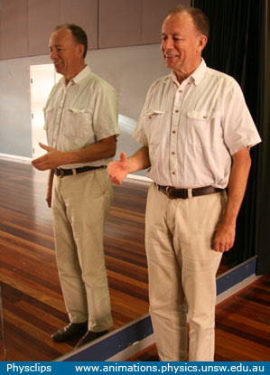
Our reflection in a (plane) mirror is a familiar example of a virtual image. The image is called virtual because the light does not really come from the position of the image. Two rays of light are traced in the diagram: at each reflection, angle of incidence equals angle of reflection. From simple geometry, we see that the image is the same size as the object (ab = a'b'). So the magnification is +1, where the '+' indicates that it is right way up. If the object were in a plane at the same distance from the mirror, we could observe that the line AB is half the length of ab. So, to see yourself in the mirror from head to toe, you need a mirror that is (at least) half as tall as you are. In the photo, you'll notice that my image appears to be smaller than me. In fact, the image is the same size, but it looks smaller because it is further away from the camera. I am about half a metre from the mirror, and, in the geometry used for this photo, the mirror and I are both the same distance from the camera. But the image is half a metre behind the mirror, so it is half a metre more distant from the camera than I am. On the sketch, the normal direction from the mirror is labelled as the x axis. Looking at the object, the nose has the least negative value of x, and the back of the head has the most negative x. Looking at the image, the reflection's nose has the smallest positive value of x, and the back of the head the most positive. So we can see that, while the image is right way up (not inverted in the plane of the mirror) it is invervted in the x direction, i.e. in the normal direction to the mirror. |
||||
Why does a mirror seem to invert left to right, but not top to bottom?In the photo at left below, my mirror image seems to offer his/my left hand to shake*. Hence the puzzle posed in the multimedia tutorial: Why should the mirror (seem to) invert left and right, but not top and bottom?
As above, let's call the normal direction from the mirror the x axis. As we saw in the diagram above, the image in the mirror is inverted in the x axis. In the photo at right, the mirror really does invert left to right: my extended right hand is closest to the mirror (least positive x) while the reflection's extended hand is also closest to the mirror. In the photo at left, the image is also inverted in the x direction, so here it is inverted front to back. Why do we look at this reflection and think that it is inverted left to right? The answer is that I am approximately symmetrical: my left side (one arm, one hand, half a head etc) is very much like my right. So, when we look at my front-to-back reflection in the photo at left, we could imagine that it is just me, but rotated 180° about a vertical axis. Except for one thing: my imagined rotation would have to put down the right hand and extend the left. For that reason, we imagine the front-to-back inverted reflection as a 180° rotation plus a left-to-right inversion. Finally, we should note that a mirror can invert top to bottom: all I'd have to do is to lie on the floor with my feet towards the mirror!
|
||||
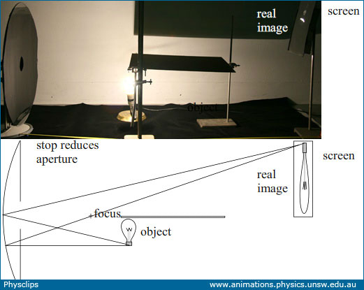
Real images in a concave mirrorA mirror can produce a real image, provided that it is a concave mirror. In this experiment, we use an incandescent lamp as the object, whose image we project onto a vertical white screen. There is a horizontal baffle between the lamp and the screen so that light from the lamp doesn't fall directly on the screen. As we'll show below in the section on Aberration, this cheap mirror is not a good approximation to a parabola, so using its whole area would produce a very distorted image. For that reason, we use a stop (a sheet of black paper) with a small hole to reduce the mirror area. The photo at top left shows a side view, and a schematic lies below. The middle photo was taken from above the mirror, looking towards the lamp and screen. A larger version of this photo is shown at right. In this version, the top half of the photo have been brightened, while the bottom half has been darkened, to show better the details of the lamp and to make it more obvious that the image is inverted. Note that rays of light really do meet at the position of this image, which is why we call it a real image.
Here the light really does fall on the screen to form the image, which is therefore a real image. (Two white lines on the photo at top right show one light path from object to image.) The object and the image are equidistant from the mirror, and this distance is twice the focal length. It is inverted. More about that below. |
||||
Parabolic reflectors
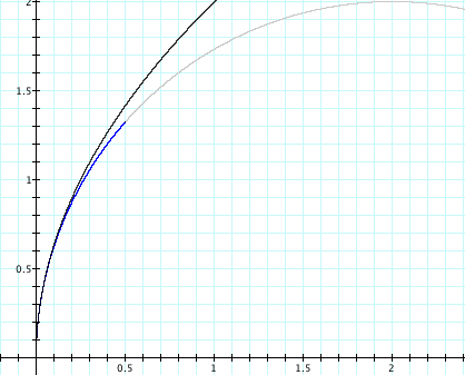
Newtonian telescopes use parabolic mirrors because the parallel light from a single, very distant star is converted by the mirror to a single point—provided that the star lies close to the axis of the parabola. The animation above shows the parabola x = y2/4, and a series of rays in the minus x direction. At the point where the ray strikes the mirror, we show the tangent to the mirror and the normal. The angle of reflection equals the angle of incidence. All rays pass through the focus, which in this case is the point (1,0). Fermat's principle states that the path followed by light from one point to another is the path that minimises the time of travel. We've seen above that, if we point a telescope at a very, very distant star, all the light that strikes the mirror point converges at that focus. Now, if all of those rays cover the distance in minimum time, then that time must be the same for all rays. And, since the speed of light is (famously) constant, that the distance must be the same. So, if you measure the distance from the right hand side of the picture to the mirror and then to the focus, it is the same for all rays.
|
||||
Focussing with a concave mirror
If this mirror were perfectly parabolic and if it were pointed directly at the sun, then it would focus the radiation onto a very small region near the focal point. The mirror is not parabolic: a good parabolic mirror of this size would be used for an extremely good amateur telescope or a research instrument such as a patrol telescope. We obtained this one cheaply for demonstrations and, for that purpose the aberration it produces is actually useful! This mirror is approximately but not very accurately spherical. We can see in this movie that the shape of the bright image is not even symmetric, so the mirror is not symmetric. Nevertheless, by minimising the size of the image formed by the parallel rays of light from the sun, we get a good measure of the focal length. The ignition of the paper is also interesting. The solar intensity or energy flux is about 1300 W.m−2, so the mirror is concentrating a few hundred watts onto the image area. After just seven seconds, the paper ignites. It follows that a mirror like this is quite dangerous, especially on a sunny day: even focussed on skin it could quickly cause pain, and directed towards the eye it could be blinding. |


How hot can we make an image using a large concave mirror?
Another puzzle from the multimedia tutorial: Suppose that we had a perfectly parabolic mirror. Ray optics tells us that, if perfectly parabolic, it would focus light on a point. The larger the mirror, the more of the sun's radiation it would focus on that very small area: in fact about 1400 watts per square metre of mirror, if we neglect clouds and scattering in the atmosphere. So, with a very small, largely insulated target, larger mirror areas would give more and more power. What is the maximum temperature we could reach? Thermodynamics tells us that there must be a limit: The temperature of the surface of the sun is about 6000 K. It were possible to heat the target to a higher temperature than that, then we could run a heat engine from the target to the sun: a perpetuum mobile (perpetual motion machine) of the second kind: it would violate the second law of thermodynamics. So there must be a catch. And there is. In later chapters, we'll analyse diffraction, which depends on the the wavelength λ of the radiation that produces it. And we'll also show how the temperature of an object is related to the wavelengths of radiation it emits (see this link for a start). |

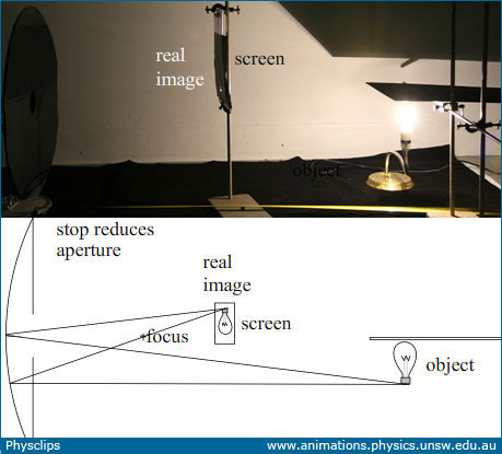
In the images above, the object is positioned at the centre of the spherical mirror, and is thus at a distance of twice the focal length. This produces an image that is also at a distance of twice the focal length. Let's now look at some different distances, then derive equations relating them.
|
||||||
The mirror equation: object, image and focal distancesCompared with that in the photo above, this photo shows the object closer to the mirror, though still further away than one focal length. The image is now further from the mirror.
In the next photo, the object is at a distance greater than two focal lengths (2f). The image now lies between f and 2f.
Let's use the geometry of the ray diagrams sketched above to derive an equation relating the object distance p, the image distance q and the focal length f. Apologies readers, I still have a diagram to make up here. Convex mirrorsThe photographs below show reflections in spherical mirrors: convex at left and concave at right. (You can compare this with the plane mirror image above.
|
||||||
|


Distortion in mirrorsThis clip, from the multimedia tutorial Geometrical Optics, shows some interesting distortions in the image produced a concave mirror. We've seen above that the magnification in the concave mirror depends on the distance of the object from the mirror. Parts of my face are much closer to the mirror than others, and so are magnified more. The non-uniform magnification of the different parts of the face are what cause the distortion, leading ultimately to the cyclopean fellow at the end of the clip. |