
13.7: The RLC Series Acceptor Circuit


- Last updated
- Mar 5, 2022
- Save as PDF

( \newcommand{\kernel}{\mathrm{null}\,}\)
A resistance, inductance and a capacitance in series is called an "acceptor" circuit, presumably because, for some combination of the parameters, the magnitude of the inductance is a minimum, and so current is accepted most readily. We see in Figure XIII.5 an alternating voltage V=ˆVejωt applied across such an R, L and C.
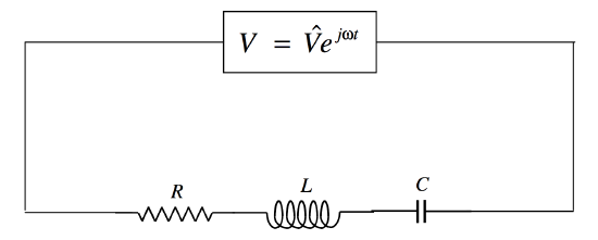
FIGURE XIII.5
The impedance is
Z=R+j(Lω−1Cω).
We can see that the voltage leads on the current if the reactance is positive; that is, if the inductive reactance is greater than the capacitive reactance; that is, if ω>1/√LC. (Recall that the frequency, ν, is ω/(2π)). If ω<1/√LC, the voltage lags behind the current. And if ω=1/√LC, the circuit is purely resistive, and voltage and current are in phase.
The magnitude of the impedance (which is equal to ˆV/ˆI) is
|Z|=√R2+(Lω−1/(Cω))2,
and this is least (and hence the current is greatest) when ω=1/√LC, the resonant frequency, which I shall denote by ω0.
It is of interest to draw a graph of how the magnitude of the impedance varies with frequency for various values of the circuit parameters. I can reduce the number of parameters by defining the dimensionless quantities
Ω=ω/ω0
Q=1R√LC
and
z=|Z|R.
You should verify that Q is indeed dimensionless. We shall see that the sharpness of the resonance depends on Q, which is known as the quality factor (hence the symbol Q). In terms of the dimensionless parameters, Equation ??? becomes
z=√1+Q2(Ω−1/Ω)2.
This is shown in Figure XIII.6, in which it can be seen that the higher the quality factor, the sharper the resonance.
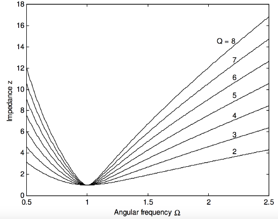
FIGURE XIII.6
In particular, it is easy to show that the frequencies at which the impedance is twice its minimum value are given by the positive solutions of
Ω4−(2+3Q2)Ω2+1=0.
If I denote the smaller and larger of these solutions by Ω− and Ω+, then Ω+−Ω− will serve as a useful description of the width of the resonance, and this is shown as a function of quality factor in Figure XIII.7.
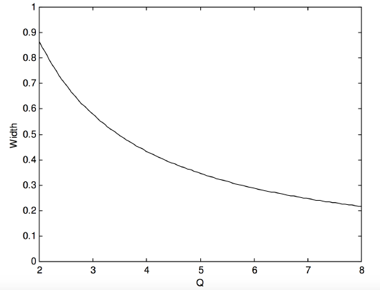
FIGURE XIII.7