
8.5: Tension in a Rope


- Last updated
- Jul 20, 2022
- Save as PDF
( \newcommand{\kernel}{\mathrm{null}\,}\)
Definition of Tension in a Rope
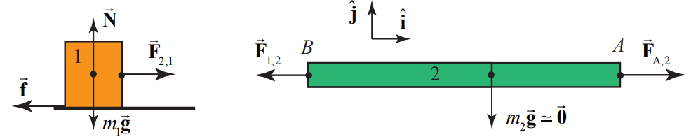
Let’s return to our example of the very light rope (object 2 with m2≃0) that is attached to a block (object 1) at the point B , and pulled by an applied force at point A →FA,2 (Figure 8.18a).

Choose a coordinate system with the ˆj-unit vector pointing upward in the normal direction to the surface, and the ˆi -unit vector pointing in the positive x -direction, (Figure 8.18b). The force diagrams for the system consisting of the rope and block is shown in Figure 8.19, and for the rope and block separately in Figure 8.20, where →F2,1 the force on the block (object 1) due to the rope (object 2), and →F1,2 is the force on the rope due to the block.

The forces on the rope and the block must each sum to zero. Because the rope is not accelerating, Newton’s Second Law applied to the rope requires that FA,2−F1,2=m2a (where we are using magnitudes for all the forces).
Because we are assuming the mass of the rope is negligible therefore
FA,2−F1,2=0; (massless rope)
If we consider the case that the rope is very light, then the forces acting at the ends of the rope are nearly horizontal. Then if the rope-block system is moving at constant speed or at rest, Newton’s Second Law is now
FA,2−F1,2=0
Newton’s Second Law applied to the block in the +ˆi-direction requires that F2,1−f=0 Newton’s Third Law, applied to the block-rope interaction pair requires that F1,2=F2,1. Therefore
FA,2=F1,2=F2,1=f
Thus the applied pulling force is transmitted through the rope to the block since it has the same magnitude as the force of the rope on the block. In addition, the applied pulling force is also equal to the friction force on the block.
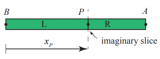
How do we define “tension” at some point in a rope? Suppose make an imaginary slice of the rope at a point P , a distance xP from point B , where the rope is attached to the block. The imaginary slice divides the rope into two sections, labeled L (left) and R (right), as shown in Figure 8.20.
There is now a Third Law pair of forces acting between the left and right sections of the rope. Denote the force acting on the left section by →FR,L(xP) and the force acting on the right section by →FL,R(xP) Newton’s Third Law requires that the forces in this interaction pair are equal in magnitude and opposite in direction.
→FR,L(xp)=−→FL,R(xP)
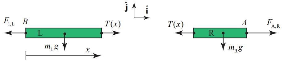
The force diagram for the left and right sections are shown in Figure 8.21 where →F1,L is the force on the left section of the rope due to the block-rope interaction. (We had previously denoted that force by →F1,2) Now denote the force on the right section of the rope side due to the pulling force at the point A by →FA,R (which we had previously denoted by →FA,2).

The tension T(xP) at a point P in rope lying a distance x from one the left end of the rope, is the magnitude of the action -reaction pair of forces acting at the point P ,
T(xp)=|→FR,L(xP)|=|→FL,R(xP)|
For a rope of negligible mass, under tension, as in the above case, (even if the rope is accelerating) the sum of the horizontal forces applied to the left section and the right section of the rope are zero, and therefore the tension is uniform and is equal to the applied pulling force,
T=FA,R
Example 8.3 Tension in a Massive Rope

Consider a block of mass m1 that is lying on a horizontal surface. The coefficient of kinetic friction between the block and the surface is μk. A uniform rope of mass m2 and length d is attached to the block. The rope is pulled from the side opposite the block with an applied force of magnitude |→FA,2|=FA,2. Because the rope is now massive, the pulling force makes an angle ϕ with respect to the horizontal in order to balance the gravitational force on the rope, (Figure 8.22a). Determine the tension in the rope as a function of distance x from the block.
Solution: In the following analysis, we shall assume that the angle ϕ is very small and depict the pulling and tension forces as essentially acting in the horizontal direction even though there must be some small vertical component to balance the gravitational forces.
The key point to realize is that the rope is now massive and we must take in to account the inertia of the rope when applying Newton’s Second Law. Consider an imaginary slice through the rope at a distance x from the block (Figure 8.22b), dividing the rope into two sections. The right section has length d−x and mass mR=(m2/d)(d−x). mR=(m2/d)(d−x). The left section has length x and mass mL=(m2/d)(x).

The free body force diagrams for the two sections of the rope are shown in Figure 8.22c, where T (x) is the tension in the rope at a distance x from the block, and F1,L=|→F1,L|≡|→F1,2| is the magnitude of the force on the left-section of the rope due to the rope-block interaction.
Apply Newton’s Second Law to the right section of the rope yielding
FA,R−T(x)=mRaR=m2d(d−x)aR
where aR is the x -component of the acceleration of the right section of the rope. Apply Newton’s Second Law to the left slice of the rope yielding
T(x)−F1,L=mLaL=(m2/d)xaL
where aL is the x -component of the acceleration of the left piece of the rope.

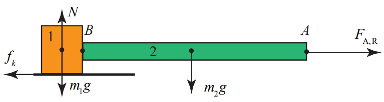
The force diagram on the block is shown in Figure 8.23. Newton’s Second Law on the block in the +ˆi- direction is FL,1−fk=m1a1 and in the +ˆj- direction is N−m1g=0 The kinetic friction force acting on the block is fk=μkN=μkm1g Newton’s Second Law on the block in the +ˆi-direction becomes
FL,1−μkm1g=m1a1
Newton’s Third Law for the block-rope interaction is given by FL,1=F1,L. Equation (8.5.8) then becomes
T(x)−(μkm1g+m1a1)=(m2/d)xaL
Because the rope and block move together, the accelerations are equal which we denote by the symbol a≡a1=aL. Then Equation (8.5.10) becomes
T(x)=μkm1g+(m1+(m2/d)x)a
This result is not unexpected because the tension is accelerating both the block and the left section and is opposed by the frictional force.
Alternatively, the force diagram on the system consisting of the rope and block is shown in Figure 8.24.
Newton’s Second Law becomes
FA,R−μkm1g=(m2+m1)a
Solve Equation (8.5.12) for FA,R and substitute into Equation (8.5.7), and solve for the tension yielding Equation (8.5.11).
Example 8.4 Tension in a Suspended Rope
A uniform rope of mass M and length L is suspended from a ceiling (Figure 8.25). The magnitude of the acceleration due to gravity is g . (a) Find the tension in the rope at the upper end where the rope is fixed to the ceiling. (b) Find the tension in the rope as a function of the distance from the ceiling. (c) Find an equation for the rate of change of the tension with respect to distance from the ceiling in terms of M , L , and g .
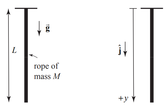
Solution: (a) Begin by choosing a coordinate system with the origin at the ceiling and the positive y -direction pointing downward (Figure 8.26). In order to find the tension at the upper end of the rope, choose as a system the entire rope. The forces acting on the rope are the force at y = 0 holding the rope up, T ( y = 0) , and the gravitational force on the entire rope. The free-body force diagram is shown in Figure 8.27.

Because the acceleration is zero, Newton’s Second Law on the rope is Mg−T(y=0)=0. Therefore the tension at the upper end is T(y=0)=Mg.
(b) Recall that the tension at a point is the magnitude of the action-reaction pair of forces acting at that point. Make an imaginary slice in the rope a distance y from the ceiling separating the rope into an upper segment 1, and lower segment 2 (Figure 8.28a). Choose the upper segment as a system with mass m1=(M/L)y The forces acting on the upper segment are the gravitational force, the force T ( y = 0) holding the rope up, and the tension T ( y) at the point y , that is pulling the upper segment down. The free-body force diagram is shown in Figure 8.28b.

Apply Newton’s Second Law to the upper segment: m1g+T(y)−T(y=0)=0. Therefore the tension at a distance y from the ceiling is T(y)=T(y=0)−m1g. Because m1=(M/L)y is the mass of the segment piece and Mg is the tension at the upper end, Newton’s Second Law becomes
T(y)=Mg(1−y/L)
As a check, we note that when y=L the tension T(y=L)=0 which is what we expect because there is no force acting at the lower end of the rope.
(c) Differentiate Equation (8.5.13) with respect to y yielding
dTdy=−(M/L)g
The rate that the tension is changing at a constant rate with respect to distance from the top of the rope.
Continuous Systems and Newton’s Second Law as a Differential Equations
We can determine the tension at a distance y from the ceiling in Example 8.4, by an alternative method, a technique that will generalize to many types of “continuous systems”. Choose a coordinate system with the origin at the ceiling and the positive y - direction pointing downward as in Figure 8.25. Consider as the system a small element of the rope between the points y and y+Δy. This small element has length Δy The small element has mass Δm=(M/L)Δy and is shown in Figure 8.29.
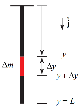
Δm=(M/L)Δy
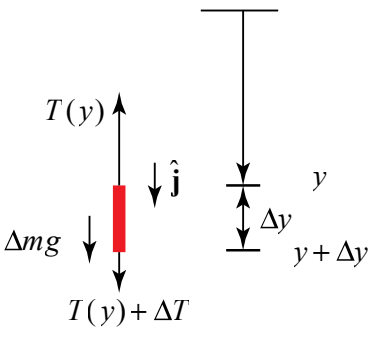
The forces acting on the small element are the tension, T (y) at y directed upward, the tension T(y+Δy) at y+Δy directed downward, and the gravitational force Δmg directed downward. The tension T(y+Δy) is equal to the tension T ( y) plus a small difference ΔT
T(y+Δy)=T(y)+ΔT
The small difference in general can be positive, zero, or negative. The free body force diagram is shown in Figure 8.30.
Now apply Newton’s Second Law to the small element
Δmg+T(y)−(T(y)+ΔT)=0
The difference in the tension is then ΔT=−Δmg. We now substitute our result for the mass of the element Δm=(M/L)Δy, and find that that
ΔT=−(M/L)Δyg
Divide through by Δy yielding ΔT/Δy=−(M/L)g. Now take the limit in which the length of the small element goes to zero, Δy→0
limΔy→0ΔTΔy=−(M/L)g
Recall that the left hand side of Equation (8.5.18) is the definition of the derivative of the tension with respect to y , and so we arrive at Equation (8.5.14),
dTdy=−(M/L)g
We can solve the differential equation, Equation (8.5.14), by a technique called separation of variables. We rewrite the equation as dT=−(M/L)gdy and integrate both sides. Our integral will be a definite integral in which we integrate a ‘dummy’ integration variable y′ and y′=0 to y′=y and the corresponding T′ from T′=T(y=0) to T′=T(y):
∫T′=T(y)T′=T(y=0)dT′=−(M/L)g∫y′=yy′=0dy′
After integration and substitution of the limits, we have that
T(y)−T(y=0)=−(M/L)gy
Us the fact that tension at the top of the rope is T(y=0)=Mg and find that
T(y)=Mg(1−y/L)
in agreement with our earlier result, Equation (8.5.13).