22.2: Gyroscope
- Page ID
- 25672
\( \newcommand{\vecs}[1]{\overset { \scriptstyle \rightharpoonup} {\mathbf{#1}} } \)
\( \newcommand{\vecd}[1]{\overset{-\!-\!\rightharpoonup}{\vphantom{a}\smash {#1}}} \)
\( \newcommand{\dsum}{\displaystyle\sum\limits} \)
\( \newcommand{\dint}{\displaystyle\int\limits} \)
\( \newcommand{\dlim}{\displaystyle\lim\limits} \)
\( \newcommand{\id}{\mathrm{id}}\) \( \newcommand{\Span}{\mathrm{span}}\)
( \newcommand{\kernel}{\mathrm{null}\,}\) \( \newcommand{\range}{\mathrm{range}\,}\)
\( \newcommand{\RealPart}{\mathrm{Re}}\) \( \newcommand{\ImaginaryPart}{\mathrm{Im}}\)
\( \newcommand{\Argument}{\mathrm{Arg}}\) \( \newcommand{\norm}[1]{\| #1 \|}\)
\( \newcommand{\inner}[2]{\langle #1, #2 \rangle}\)
\( \newcommand{\Span}{\mathrm{span}}\)
\( \newcommand{\id}{\mathrm{id}}\)
\( \newcommand{\Span}{\mathrm{span}}\)
\( \newcommand{\kernel}{\mathrm{null}\,}\)
\( \newcommand{\range}{\mathrm{range}\,}\)
\( \newcommand{\RealPart}{\mathrm{Re}}\)
\( \newcommand{\ImaginaryPart}{\mathrm{Im}}\)
\( \newcommand{\Argument}{\mathrm{Arg}}\)
\( \newcommand{\norm}[1]{\| #1 \|}\)
\( \newcommand{\inner}[2]{\langle #1, #2 \rangle}\)
\( \newcommand{\Span}{\mathrm{span}}\) \( \newcommand{\AA}{\unicode[.8,0]{x212B}}\)
\( \newcommand{\vectorA}[1]{\vec{#1}} % arrow\)
\( \newcommand{\vectorAt}[1]{\vec{\text{#1}}} % arrow\)
\( \newcommand{\vectorB}[1]{\overset { \scriptstyle \rightharpoonup} {\mathbf{#1}} } \)
\( \newcommand{\vectorC}[1]{\textbf{#1}} \)
\( \newcommand{\vectorD}[1]{\overrightarrow{#1}} \)
\( \newcommand{\vectorDt}[1]{\overrightarrow{\text{#1}}} \)
\( \newcommand{\vectE}[1]{\overset{-\!-\!\rightharpoonup}{\vphantom{a}\smash{\mathbf {#1}}}} \)
\( \newcommand{\vecs}[1]{\overset { \scriptstyle \rightharpoonup} {\mathbf{#1}} } \)
\(\newcommand{\longvect}{\overrightarrow}\)
\( \newcommand{\vecd}[1]{\overset{-\!-\!\rightharpoonup}{\vphantom{a}\smash {#1}}} \)
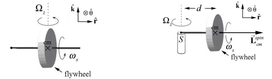
\(\newcommand{\avec}{\mathbf a}\) \(\newcommand{\bvec}{\mathbf b}\) \(\newcommand{\cvec}{\mathbf c}\) \(\newcommand{\dvec}{\mathbf d}\) \(\newcommand{\dtil}{\widetilde{\mathbf d}}\) \(\newcommand{\evec}{\mathbf e}\) \(\newcommand{\fvec}{\mathbf f}\) \(\newcommand{\nvec}{\mathbf n}\) \(\newcommand{\pvec}{\mathbf p}\) \(\newcommand{\qvec}{\mathbf q}\) \(\newcommand{\svec}{\mathbf s}\) \(\newcommand{\tvec}{\mathbf t}\) \(\newcommand{\uvec}{\mathbf u}\) \(\newcommand{\vvec}{\mathbf v}\) \(\newcommand{\wvec}{\mathbf w}\) \(\newcommand{\xvec}{\mathbf x}\) \(\newcommand{\yvec}{\mathbf y}\) \(\newcommand{\zvec}{\mathbf z}\) \(\newcommand{\rvec}{\mathbf r}\) \(\newcommand{\mvec}{\mathbf m}\) \(\newcommand{\zerovec}{\mathbf 0}\) \(\newcommand{\onevec}{\mathbf 1}\) \(\newcommand{\real}{\mathbb R}\) \(\newcommand{\twovec}[2]{\left[\begin{array}{r}#1 \\ #2 \end{array}\right]}\) \(\newcommand{\ctwovec}[2]{\left[\begin{array}{c}#1 \\ #2 \end{array}\right]}\) \(\newcommand{\threevec}[3]{\left[\begin{array}{r}#1 \\ #2 \\ #3 \end{array}\right]}\) \(\newcommand{\cthreevec}[3]{\left[\begin{array}{c}#1 \\ #2 \\ #3 \end{array}\right]}\) \(\newcommand{\fourvec}[4]{\left[\begin{array}{r}#1 \\ #2 \\ #3 \\ #4 \end{array}\right]}\) \(\newcommand{\cfourvec}[4]{\left[\begin{array}{c}#1 \\ #2 \\ #3 \\ #4 \end{array}\right]}\) \(\newcommand{\fivevec}[5]{\left[\begin{array}{r}#1 \\ #2 \\ #3 \\ #4 \\ #5 \\ \end{array}\right]}\) \(\newcommand{\cfivevec}[5]{\left[\begin{array}{c}#1 \\ #2 \\ #3 \\ #4 \\ #5 \\ \end{array}\right]}\) \(\newcommand{\mattwo}[4]{\left[\begin{array}{rr}#1 \amp #2 \\ #3 \amp #4 \\ \end{array}\right]}\) \(\newcommand{\laspan}[1]{\text{Span}\{#1\}}\) \(\newcommand{\bcal}{\cal B}\) \(\newcommand{\ccal}{\cal C}\) \(\newcommand{\scal}{\cal S}\) \(\newcommand{\wcal}{\cal W}\) \(\newcommand{\ecal}{\cal E}\) \(\newcommand{\coords}[2]{\left\{#1\right\}_{#2}}\) \(\newcommand{\gray}[1]{\color{gray}{#1}}\) \(\newcommand{\lgray}[1]{\color{lightgray}{#1}}\) \(\newcommand{\rank}{\operatorname{rank}}\) \(\newcommand{\row}{\text{Row}}\) \(\newcommand{\col}{\text{Col}}\) \(\renewcommand{\row}{\text{Row}}\) \(\newcommand{\nul}{\text{Nul}}\) \(\newcommand{\var}{\text{Var}}\) \(\newcommand{\corr}{\text{corr}}\) \(\newcommand{\len}[1]{\left|#1\right|}\) \(\newcommand{\bbar}{\overline{\bvec}}\) \(\newcommand{\bhat}{\widehat{\bvec}}\) \(\newcommand{\bperp}{\bvec^\perp}\) \(\newcommand{\xhat}{\widehat{\xvec}}\) \(\newcommand{\vhat}{\widehat{\vvec}}\) \(\newcommand{\uhat}{\widehat{\uvec}}\) \(\newcommand{\what}{\widehat{\wvec}}\) \(\newcommand{\Sighat}{\widehat{\Sigma}}\) \(\newcommand{\lt}{<}\) \(\newcommand{\gt}{>}\) \(\newcommand{\amp}{&}\) \(\definecolor{fillinmathshade}{gray}{0.9}\)A toy gyroscope of mass \(m\) consists of a spinning flywheel mounted in a suspension frame that allows the flywheel’s axle to point in any direction. One end of the axle is supported on a pylon \(a\) distance \(d\) from the center of mass of the gyroscope.
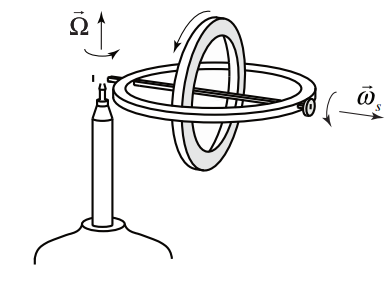
Choose polar coordinates so that the axle of the gyroscope flywheel is aligned along the r-axis and the vertical axis is the z -axis (Figure 22.2 shows a schematic representation of the gyroscope).
The flywheel is spinning about its axis with a spin angular velocity,
\[\overrightarrow{\boldsymbol{\omega}}_{s}=\omega_{s} \hat{\mathbf{r}} \nonumber \]
where \(\omega_{s}\) is the radial component and \(\omega_{s}>0\) for the case illustrated in Figure 22.2.
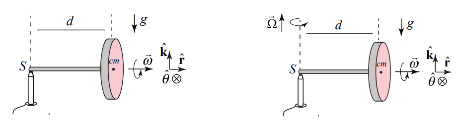
When we release the gyroscope it undergoes a very surprising motion. Instead of falling downward, the center of mass rotates about a vertical axis that passes through the contact point \(S\) of the axle with the pylon with a precessional angular velocity
\[\overrightarrow{\boldsymbol{\Omega}}=\Omega_{z} \hat{\mathbf{k}}=\frac{d \theta}{d t} \hat{\mathbf{k}} \nonumber \]
where \(\Omega_{z}=d \theta / d t\) is the z -component and \(\Omega_{z}>0\) for the case illustrated in Figure 22.3. Therefore the angular velocity of the flywheel is the sum of these two contributions
\[\overrightarrow{\boldsymbol{\omega}}=\overrightarrow{\boldsymbol{\omega}}_{s}+\overrightarrow{\boldsymbol{\Omega}}=\omega_{s} \hat{\mathbf{r}}+\Omega_{z} \hat{\mathbf{k}} \nonumber \]
We shall study the special case where the magnitude of the precession component \(\left|\Omega_{z}\right|\) of the angular velocity is much less than the magnitude of the spin component \(\left|\omega_{s}\right|\) of the spin angular velocity, \(\left|\Omega_{z}\right|<<\mid \omega_{s}\), so that the magnitude of the angular velocity \(|\vec{\omega}| \simeq\left|\omega_{\mathrm{s}}\right| \text { and } \Omega_{z} \text { and } \omega_{s}\) nearly constant. These assumptions are collectively called the gyroscopic approximation.
The force diagram for the gyroscope is shown in Figure 22.4. The gravitational force acts at the center of the mass and is directed downward, \(\overrightarrow{\mathbf{F}}^{g}=-m g \hat{\mathbf{k}}\). There is also a contact force, \(\overrightarrow{\mathbf{F}}^{c}\) between the end of the axle and the pylon. It may seem that the contact force, \(\overrightarrow{\mathbf{F}}^{c}\) has only an upward component, \(\overrightarrow{\mathbf{F}}^{v}=F_{z} \hat{\mathbf{k}}\), but as we shall soon see there must also be a radial inward component to the contact force, \(\overrightarrow{\mathbf{F}}^{r}=F_{r} \hat{\mathbf{r}}, \text { with } F_{r}<0\) because the center of mass undergoes circular motion.
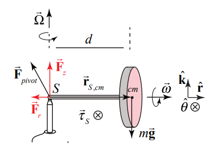
The reason that the gyroscope does not fall down is that the vertical component of the contact force exactly balances the gravitational force
\[F_{z}-m g=0 \nonumber \]
What about the torque about the contact point \(S\) ? The contact force acts at \(S\) so it does not contribute to the torque about \(S\) ; only the gravitational force contributes to the torque about \(S\) (Figure 22.5b). The direction of the torque about \(S\) is given by
\[\vec{\tau}_{S}=\overrightarrow{\mathbf{r}}_{S, \mathrm{cm}} \times \overrightarrow{\mathbf{F}}_{\mathrm{gravity}}=d \hat{\mathbf{r}} \times m g(-\hat{\mathbf{k}})=d m g \hat{\boldsymbol{\theta}} \nonumber \]
and is in the positive \(\hat{\boldsymbol{\theta}}\)-direction. However we know that if there a non-zero torque about \(S\), then the angular momentum about \(S\) must change in time, according to
\[\vec{\tau}_{S}=\frac{d \overrightarrow{\mathrm{L}}_{S}}{d t} \nonumber \]
The angular momentum about the point \(S\) of the gyroscope is given by
\[\overrightarrow{\mathbf{L}}_{S}=\overrightarrow{\mathbf{L}}_{S}^{\text {otbital }}+\overrightarrow{\mathbf{L}}_{\mathrm{cm}}^{\text {spin }} \nonumber \]
The orbital angular momentum about the point \(S\) is
\[\overrightarrow{\mathbf{L}}_{S}^{\text {otbial }}=\overrightarrow{\mathbf{r}}_{S, c m} \times m \overrightarrow{\mathbf{v}}_{c m}=d \hat{\mathbf{r}} \times m d \Omega_{z} \hat{\boldsymbol{\theta}}=m d^{2} \Omega_{z} \hat{\mathbf{k}} \nonumber \]
The magnitude of the orbital angular momentum about \(S\) is nearly constant and the direction does not change. Therefore
\[\frac{d}{d t} \overrightarrow{\mathbf{L}}_{S}^{\text {obital }}=\overrightarrow{\mathbf{0}} \nonumber \]
The spin angular momentum includes two terms. Recall that the flywheel undergoes two separate rotations about different axes. It is spinning about the flywheel axis with spin angular velocity \(\overrightarrow{\boldsymbol{\omega}}_{s}\). As the flywheel precesses around the pivot point, the flywheel rotates about the z -axis with precessional angular velocity \(\overrightarrow{\mathbf{\Omega}}\) (Figure 22.5). The spin angular momentum therefore is given by
\[\overrightarrow{\mathbf{L}}_{\mathrm{cm}}^{\operatorname{spin}}=I_{r} \omega_{s} \hat{\mathbf{r}}+I_{z} \Omega_{z} \hat{\mathbf{k}} \nonumber \]
where \(I_{r}\) is the moment of inertia with respect to the flywheel axis and \(I_{z}\) is the moment of inertia with respect to the z -axis. If we assume the axle is massless and the flywheel is uniform with radius R, then \(I_{r}=(1 / 2) m R^{2}\). By the perpendicular axis theorem \(I_{r}=I_{z}+I_{y}=2 I_{z}\) hence \(I_{z}=(1 / 4) m R^{2}\).
Recall that the gyroscopic approximation holds when \(\left|\Omega_{z}\right|<<\left|\omega_{s}\right|\) which implies that \(I_{z} \Omega_{z}<<I_{r} \omega_{s}\) and therefore we can ignore the contribution to the spin angular momentum from the rotation about the vertical axis, and so
\[\overrightarrow{\mathbf{L}}_{\mathrm{cm}}^{\operatorname{spin}} \simeq I_{\mathrm{cm}} \omega_{s} \hat{\mathbf{r}} \nonumber \]
(The contribution to the spin angular momentum due to the rotation about the z -axis, \(I_{z} \Omega_{z} \hat{\mathbf{k}}\) is nearly constant in both magnitude and direction so it does not change in time, \(d\left(I_{z} \Omega_{z} \hat{\mathbf{k}}\right) / d t \simeq \overrightarrow{\mathbf{0}}\). Therefore the angular momentum about \(S\) is approximately
\[\overrightarrow{\mathbf{L}}_{S} \simeq \overrightarrow{\mathbf{L}}_{\mathrm{cm}}^{\mathrm{spin}}=I_{\mathrm{cm}} \omega_{s} \hat{\mathbf{r}} \nonumber \]
Our initial expectation that the gyroscope should fall downward due to the torque that the gravitational force exerts about the contact point \(S\) leads to a violation of the torque law. If the center of mass did start to fall then the change in the spin angular momentum, \(\Delta \overrightarrow{\mathbf{L}}_{\mathrm{cm}}^{\operatorname{spin}}\) would point in the negative z -direction and that would contradict the vector aspect of Equation (22.2.6). Instead of falling down, the angular momentum about the center of mass, \(\overrightarrow{\mathbf{L}}_{\mathrm{cm}}^{\mathrm{spin}}\) must change direction such that the direction of \(\Delta \overrightarrow{\mathbf{L}}_{\mathrm{cm}}^{\text {spin }}\) is in the same direction as torque about \(S\) (Equation (22.2.5)), the positive \(\hat{\boldsymbol{\theta}}\)-direction.
Recall that in our study of circular motion, we have already encountered several examples in which the direction of a constant magnitude vector changes. We considered a point object of mass m moving in a circle of radius r . When we choose a coordinate system with an origin at the center of the circle, the position vector \(\overrightarrow{\mathbf{r}}\) is directed radially outward. As the mass moves in a circle, the position vector has a constant magnitude but changes in direction. The velocity vector is given by
\[\overrightarrow{\mathbf{v}}=\frac{d \overrightarrow{\mathbf{r}}}{d t}=\frac{d}{d t}(r \hat{\mathbf{r}})=r \frac{d \theta}{d t} \hat{\boldsymbol{\theta}}=r \omega_{z} \hat{\boldsymbol{\theta}} \nonumber \]
and has direction that is perpendicular to the position vector (tangent to the circle), (Figure 22.7a)).
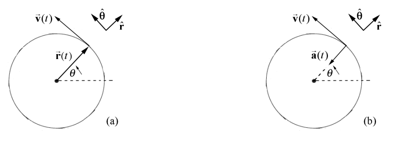
For uniform circular motion, the magnitude of the velocity is constant but the direction constantly changes and we found that the acceleration is given by (Figure 22.7b)
\[\overrightarrow{\mathbf{a}}=\frac{d \overrightarrow{\mathbf{v}}}{d t}=\frac{d}{d t}\left(v_{\theta} \hat{\boldsymbol{\theta}}\right)=v_{\theta} \frac{d \theta}{d t}(-\hat{\mathbf{r}})=r \omega_{z} \omega_{z}(-\hat{\mathbf{r}})=-r \omega_{z}^{2} \hat{\mathbf{r}} \nonumber \]
Note that we used the facts that
\[\begin{array}{l}
\frac{d \hat{\mathbf{r}}}{d t}=\frac{d \theta}{d t} \hat{\boldsymbol{\theta}} \\
\frac{d \hat{\boldsymbol{\theta}}}{d t}=-\frac{d \theta}{d t} \hat{\mathbf{r}}
\end{array} \nonumber \]
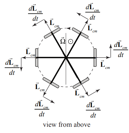
in Equations (22.2.13) and (22.2.14). We can apply the same reasoning to how the spin angular changes in time (Figure 22.8).
The time derivative of the spin angular momentum is given by
\[\frac{d \overrightarrow{\mathbf{L}}_{S}}{d t}=\frac{d \overrightarrow{\mathbf{L}}_{\mathrm{cm}, \omega_{s}}^{\operatorname{spin}}}{d t}=\left|\overrightarrow{\mathbf{L}}_{\mathrm{cm}, \omega_{s}}^{\sin }\right| \frac{d \theta}{d t} \hat{\boldsymbol{\theta}}=\left|\overrightarrow{\mathbf{L}}_{\mathrm{cm}, \omega_{s}}^{\sin }\right| \Omega_{z} \hat{\boldsymbol{\theta}}=I_{r} \omega_{s} \Omega_{z} \hat{\boldsymbol{\theta}} \nonumber \]
where \(\Omega_{z}=d \theta / d t\) is the z -component and \(\Omega_{z}>0\). The center of mass of the flywheel rotates about a vertical axis that passes through the contact point \(S\) of the axle with the pylon with a precessional angular velocity.
\[\overrightarrow{\mathbf{Q}}=\Omega_{z} \hat{\mathbf{k}}=\frac{d \theta}{d t} \hat{\mathbf{k}} \nonumber \]
Substitute Equations (22.2.16) and (22.2.5) into Equation (22.2.6) yielding
\[d m g \hat{\boldsymbol{\theta}}=\left|\overrightarrow{\mathbf{L}}_{\mathrm{cm}}^{\sin }\right| \Omega_{z} \hat{\boldsymbol{\theta}} \nonumber \]
Solving Equation (22.2.18) for the z -component of the precessional angular velocity of the gyroscope yields
\[\Omega_{z}=\frac{d m g}{\left|\overrightarrow{\mathbf{L}}_{\mathrm{cm}}^{\mathrm{spin}}\right|}=\frac{d m g}{I_{\mathrm{cm}} \omega_{\mathrm{s}}} \nonumber \]