
22.4: Worked Examples

( \newcommand{\kernel}{\mathrm{null}\,}\)
Example 22.3 Tilted Toy Gyroscope
A wheel is at one end of an axle of length d . The axle is pivoted at an angle φ with respect to the vertical. The wheel is set into motion so that it executes uniform precession; that is, the wheel’s center of mass moves with uniform circular motion with z -component of precessional angular velocity Ωz. The wheel has mass m and moment of inertia Icm about its center of mass. Its spin angular velocity →ωs has magnitude ωs and is directed as shown in Figure 22.21. Assume that the gyroscope approximation holds, |Ωz|<<ωs. Neglect the mass of the axle. What is the z -component of the precessional angular velocity Ωzz ? Does the gyroscope rotate clockwise or counterclockwise about the vertical axis (as seen from above)?
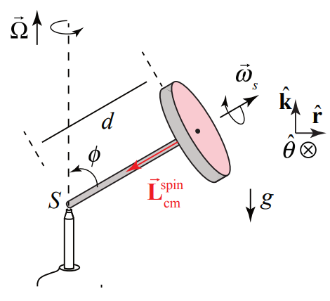
Solution: The gravitational force acts at the center of mass and is directed downward, →Fg=−mgˆk Let S denote the contact point between the pylon and the axle. The contact force between the pylon and the axle is acting at S so it does not contribute to the torque about S. Only the gravitational force contributes to the torque. Let’s choose cylindrical coordinates. The torque about S is
→τS=→rS,cm×→Fg=(dsinϕˆr+dcosϕˆk)×mg(−ˆk)=mgdsinϕˆθ
which is into the page in Figure 22.21. Because we are assuming that |Ωz|<<ωs we only consider contribution from the spinning about the flywheel axle to the spin angular momentum,
→ωs=−ωssinϕˆr−ωscosϕˆk
The spin angular momentum has a vertical and radial component,
→Lspincm=−Icmωssinϕˆr−Icmωscosϕˆk
We assume that the spin angular velocity ωs is constant. As the wheel precesses, the time derivative of the spin angular momentum arises from the change in the direction of the radial component of the spin angular momentum,
ddt→Lsincm=−Icmωssinϕdˆrdt=−Icmωssinϕdθdtˆθ
where we used the fact that
dˆrdt=dθdtˆθ
The z -component of the angular velocity of the flywheel about the vertical axis is defined to be
Ωz≡dθdt
Therefore the rate of change of the spin angular momentum is then
ddt→Lspincm=−IcmωssinϕΩzˆθ
The torque about S induces the spin angular momentum about S to change,
→τS=d→Lspincmdt
Now substitute Equation (22.4.1) for the torque about S, and Equation (22.4.7) for the rate of change of the spin angular momentum into Equation (22.4.8), yielding
mgdsinϕˆθ=−IcmωssinϕΩzˆθ
Solving Equation (22.2.18) for the z -component of the precessional angular velocity of the gyroscope yields
Ωz=−dmgIcmωs
The z -component of the precessional angular velocity is independent of the angle ϕ Because Ωz<0, the direction of the precessional angular velocity, →Ω=Ωzˆk is in the negative z -direction. That means that the gyroscope precesses in the clockwise direction when seen from above (Figure 21.22).
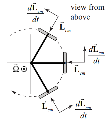
Both the torque and the time derivative of the spin angular momentum point in the ˆθ-direction indicating that the gyroscope will precess clockwise when seen from above in agreement with the calculation that Ωz<0.
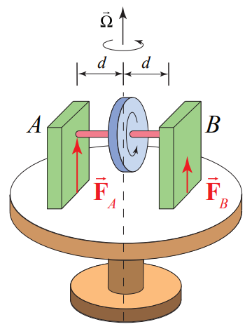
Example 22.4 Gyroscope on Rotating Platform
A gyroscope consists of an axle of negligible mass and a disk of mass M and radius R mounted on a platform that rotates with angular speed Ω. The gyroscope is spinning with angular speed ω. Forces Fa and Fb act on the gyroscopic mounts. What are the magnitudes of the forces Fa and Fb (Figure 22.22)? You may assume that the moment of inertia of the gyroscope about an axis passing through the center of mass normal to the plane of the disk is given by Icm
Solution: Figure 22.23 shows a choice of coordinate system and force diagram on the gyroscope.
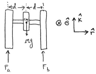
The vertical forces sum to zero since there is no vertical motion
Fa+Fb−Mg=0
Using the coordinate system depicted in the Figure 22.23, torque about the center of mass is
→τcm=d(Fa−Fb)ˆθ
The spin angular momentum is (gyroscopic approximation)
→Lspincm≃Icmωˆr
Looking down on the gyroscope from above (Figure 2.23), the radial component of the angular momentum about the center of mass is rotating counterclockwise.
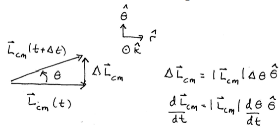
During a very short time interval Δt, the change in the spin angular momentum is Δ→Lspincm=IcmωΔθˆθ (Figure 22.24). Taking limits we have that
d→Lspincmdt=limΔt→0Δ→LspincmΔt=limΔt→0IcmωΔθΔtˆθ=Icmωdθdtˆθ
We can now apply the torque law
→τcm=d→Lspincmdt
Substitute Equations (22.4.12) and (22.4.14) into Equation (22.4.15) and just taking the component of the resulting vector equation yields
d(Fa−Fb)=IcmωΩz
We can divide Equation (22.4.16) by the quantity d yielding
Fa−Fb=IcmωΩzd
We can now use Equations (22.4.17) and (22.4.11) to solve for the forces Fa and Fb
Fa=12(Mg+IcmωΩzd)
Fb=12(Mg−IcmωΩzd)
Note that if Ωz=Mgd/Icmω then Fb=0 and one could remove the right hand support in the Figure 22.22. The simple pivoted gyroscope that we already analyzed Section 22.2 satisfied this condition. The forces we just found are the forces that the mounts must exert on the gyroscope in order to cause it to move in the desired direction. It is important to understand that the gyroscope is exerting equal and opposite forces on the mounts, i.e. the structure that is holding it. This is a manifestation of Newton’s Third Law.
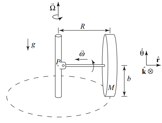
Example 22.5 Grain Mill
In a mill, grain is ground by a massive wheel that rolls without slipping in a circle on a flat horizontal millstone driven by a vertical shaft. The rolling wheel has mass M , radius b and is constrained to roll in a horizontal circle of radius R at angular speed Ω (Figure 22.25). The wheel pushes down on the lower millstone with a force equal to twice its weight (normal force). The mass of the axle of the wheel can be neglected. What is the precessional angular frequency Ω ?
Solution: Figure 22.5 shows the pivot point along with some convenient coordinate axes. For rolling without slipping, the speed of the center of mass of the wheel is related to the angular spin speed by
vcm=bω
Also the speed of the center of mass is related to the angular speed about the vertical axis associated with the circular motion of the center of mass by
vcm=RΩ
Therefore equating Equations (22.4.20) and (22.4.21) we have that
ω=ΩR/b
Assuming a uniform millwheel, Icm=(1/2)Mb2, the magnitude of the horizontal component of the spin angular momentum about the center of mass is
Lsincm=Icmω=12Mb2ω=12ΩMRb
The horizontal component of →Lspincm is directed inward, and in vector form is given by
→Lspincm=−ΩMRb2ˆr
The axle exerts both a force and torque on the wheel, and this force and torque would be quite complicated. That’s why we consider the forces and torques on the axle/wheel combination. The normal force of the wheel on the ground is equal in magnitude to Nw,G=2mg so the third-law counterpart; the normal force of the ground on the wheel has the same magnitude NG,w=2mg The joint (or hinge) at point P therefore must exert a force →FH,A on the end of the axle that has two components, an inward force →F2 to maintain the circular motion and a downward force →F1 to reflect that the upward normal force is larger in magnitude than the weight (Figure 22.26).
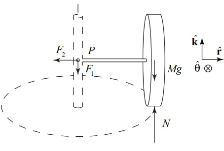
About point P,→FHA exerts no torque. The normal force exerts a torque of magnitude NG,wR=2mgR, directed out of the page, or, in vector form, →τP,N=−2mgRˆθ The weight exerts a toque of magnitude mgR , directed into the page, or, in vector form, →τP,mg=mgRˆθ. The torque about P is then
→τP=→τP,N+→τP,mg=−2mgRˆθ+mgRˆθ=−mgRˆθ
As the wheel rolls, the horizontal component of the angular momentum about the center of mass will rotate, and the inward-directed vector will change in the negative ˆθ-direction. The angular momentum about the point P has orbital and spin decomposition
→Lp=→Lotbial p+→Lspincm
The orbital angular momentum about the point P is
→Lorbital P=→rP,cm×m→vcm=Rˆr×mbΩˆθ=mRbΩzˆk
The magnitude of the orbital angular momentum about P is nearly constant and the direction does not change. Therefore
d→Lorbital Pdt=→0
Therefore the change in angular momentum about the point P is
d→Lpdt=d→Lsincmdt=ddt(ΩmRb2(−ˆr))=12ΩmRbΩ(−ˆθ)
where we used Equation (22.4.24) for the magnitude of the horizontal component of the angular momentum about the center of mass. This is consistent with the torque about P pointing out of the plane of Figure 22.26. We can now apply the rotational equation of motion,
→τP=d→LPdt
Substitute Equations(22.4.25) and (22.4.29) into Equation (22.4.30) yielding
mgR(−ˆθ)=12Ω2mRb(−ˆθ)
We can now solve Equation (22.4.31) for the angular speed about the vertical axis
Ω=√2gb