
13.23: Symmetric rigid rotor subject to torque about a fixed point
- Page ID
- 30810

\( \newcommand{\vecs}[1]{\overset { \scriptstyle \rightharpoonup} {\mathbf{#1}} } \)
\( \newcommand{\vecd}[1]{\overset{-\!-\!\rightharpoonup}{\vphantom{a}\smash {#1}}} \)
\( \newcommand{\dsum}{\displaystyle\sum\limits} \)
\( \newcommand{\dint}{\displaystyle\int\limits} \)
\( \newcommand{\dlim}{\displaystyle\lim\limits} \)
\( \newcommand{\id}{\mathrm{id}}\) \( \newcommand{\Span}{\mathrm{span}}\)
( \newcommand{\kernel}{\mathrm{null}\,}\) \( \newcommand{\range}{\mathrm{range}\,}\)
\( \newcommand{\RealPart}{\mathrm{Re}}\) \( \newcommand{\ImaginaryPart}{\mathrm{Im}}\)
\( \newcommand{\Argument}{\mathrm{Arg}}\) \( \newcommand{\norm}[1]{\| #1 \|}\)
\( \newcommand{\inner}[2]{\langle #1, #2 \rangle}\)
\( \newcommand{\Span}{\mathrm{span}}\)
\( \newcommand{\id}{\mathrm{id}}\)
\( \newcommand{\Span}{\mathrm{span}}\)
\( \newcommand{\kernel}{\mathrm{null}\,}\)
\( \newcommand{\range}{\mathrm{range}\,}\)
\( \newcommand{\RealPart}{\mathrm{Re}}\)
\( \newcommand{\ImaginaryPart}{\mathrm{Im}}\)
\( \newcommand{\Argument}{\mathrm{Arg}}\)
\( \newcommand{\norm}[1]{\| #1 \|}\)
\( \newcommand{\inner}[2]{\langle #1, #2 \rangle}\)
\( \newcommand{\Span}{\mathrm{span}}\) \( \newcommand{\AA}{\unicode[.8,0]{x212B}}\)
\( \newcommand{\vectorA}[1]{\vec{#1}} % arrow\)
\( \newcommand{\vectorAt}[1]{\vec{\text{#1}}} % arrow\)
\( \newcommand{\vectorB}[1]{\overset { \scriptstyle \rightharpoonup} {\mathbf{#1}} } \)
\( \newcommand{\vectorC}[1]{\textbf{#1}} \)
\( \newcommand{\vectorD}[1]{\overrightarrow{#1}} \)
\( \newcommand{\vectorDt}[1]{\overrightarrow{\text{#1}}} \)
\( \newcommand{\vectE}[1]{\overset{-\!-\!\rightharpoonup}{\vphantom{a}\smash{\mathbf {#1}}}} \)
\( \newcommand{\vecs}[1]{\overset { \scriptstyle \rightharpoonup} {\mathbf{#1}} } \)
\(\newcommand{\longvect}{\overrightarrow}\)
\( \newcommand{\vecd}[1]{\overset{-\!-\!\rightharpoonup}{\vphantom{a}\smash {#1}}} \)
\(\newcommand{\avec}{\mathbf a}\) \(\newcommand{\bvec}{\mathbf b}\) \(\newcommand{\cvec}{\mathbf c}\) \(\newcommand{\dvec}{\mathbf d}\) \(\newcommand{\dtil}{\widetilde{\mathbf d}}\) \(\newcommand{\evec}{\mathbf e}\) \(\newcommand{\fvec}{\mathbf f}\) \(\newcommand{\nvec}{\mathbf n}\) \(\newcommand{\pvec}{\mathbf p}\) \(\newcommand{\qvec}{\mathbf q}\) \(\newcommand{\svec}{\mathbf s}\) \(\newcommand{\tvec}{\mathbf t}\) \(\newcommand{\uvec}{\mathbf u}\) \(\newcommand{\vvec}{\mathbf v}\) \(\newcommand{\wvec}{\mathbf w}\) \(\newcommand{\xvec}{\mathbf x}\) \(\newcommand{\yvec}{\mathbf y}\) \(\newcommand{\zvec}{\mathbf z}\) \(\newcommand{\rvec}{\mathbf r}\) \(\newcommand{\mvec}{\mathbf m}\) \(\newcommand{\zerovec}{\mathbf 0}\) \(\newcommand{\onevec}{\mathbf 1}\) \(\newcommand{\real}{\mathbb R}\) \(\newcommand{\twovec}[2]{\left[\begin{array}{r}#1 \\ #2 \end{array}\right]}\) \(\newcommand{\ctwovec}[2]{\left[\begin{array}{c}#1 \\ #2 \end{array}\right]}\) \(\newcommand{\threevec}[3]{\left[\begin{array}{r}#1 \\ #2 \\ #3 \end{array}\right]}\) \(\newcommand{\cthreevec}[3]{\left[\begin{array}{c}#1 \\ #2 \\ #3 \end{array}\right]}\) \(\newcommand{\fourvec}[4]{\left[\begin{array}{r}#1 \\ #2 \\ #3 \\ #4 \end{array}\right]}\) \(\newcommand{\cfourvec}[4]{\left[\begin{array}{c}#1 \\ #2 \\ #3 \\ #4 \end{array}\right]}\) \(\newcommand{\fivevec}[5]{\left[\begin{array}{r}#1 \\ #2 \\ #3 \\ #4 \\ #5 \\ \end{array}\right]}\) \(\newcommand{\cfivevec}[5]{\left[\begin{array}{c}#1 \\ #2 \\ #3 \\ #4 \\ #5 \\ \end{array}\right]}\) \(\newcommand{\mattwo}[4]{\left[\begin{array}{rr}#1 \amp #2 \\ #3 \amp #4 \\ \end{array}\right]}\) \(\newcommand{\laspan}[1]{\text{Span}\{#1\}}\) \(\newcommand{\bcal}{\cal B}\) \(\newcommand{\ccal}{\cal C}\) \(\newcommand{\scal}{\cal S}\) \(\newcommand{\wcal}{\cal W}\) \(\newcommand{\ecal}{\cal E}\) \(\newcommand{\coords}[2]{\left\{#1\right\}_{#2}}\) \(\newcommand{\gray}[1]{\color{gray}{#1}}\) \(\newcommand{\lgray}[1]{\color{lightgray}{#1}}\) \(\newcommand{\rank}{\operatorname{rank}}\) \(\newcommand{\row}{\text{Row}}\) \(\newcommand{\col}{\text{Col}}\) \(\renewcommand{\row}{\text{Row}}\) \(\newcommand{\nul}{\text{Nul}}\) \(\newcommand{\var}{\text{Var}}\) \(\newcommand{\corr}{\text{corr}}\) \(\newcommand{\len}[1]{\left|#1\right|}\) \(\newcommand{\bbar}{\overline{\bvec}}\) \(\newcommand{\bhat}{\widehat{\bvec}}\) \(\newcommand{\bperp}{\bvec^\perp}\) \(\newcommand{\xhat}{\widehat{\xvec}}\) \(\newcommand{\vhat}{\widehat{\vvec}}\) \(\newcommand{\uhat}{\widehat{\uvec}}\) \(\newcommand{\what}{\widehat{\wvec}}\) \(\newcommand{\Sighat}{\widehat{\Sigma}}\) \(\newcommand{\lt}{<}\) \(\newcommand{\gt}{>}\) \(\newcommand{\amp}{&}\) \(\definecolor{fillinmathshade}{gray}{0.9}\)The motion of a symmetric top rotating in a gravitational field, with one point at a fixed location, is encountered frequently in rotational motion. Examples are the gyroscope and a child’s spinning top. Rotation of a rigid rotor subject to torque about a fixed point, is a case where it is necessary to take the inertia tensor with respect to the fixed point in the body, and not at the center of mass.
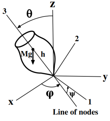
Consider the geometry, shown in Figure \(\PageIndex{1}\), where the symmetric top of mass \(M\) is spinning about a fixed tip that is displaced by a distance \(h\) from the center of mass. The tip of the top is assumed to be at the origin of both the space-fixed frame \((x, y, z)\) and the body-fixed frame \((1, 2, 3)\). Assume that the translational velocity is zero and let the principal moments about the fixed point of the symmetric top be \(I_1 = I_2 \neq I_3\).
The Lagrange equations of motion can be derived assuming that the kinetic energy equals the rotational kinetic energy, that is, it is assumed that the translational kinetic energy \(T_{trans} = 0\). Then the kinetic energy of an inertially-symmetric rigid rotor can be derived for the torque-free symmetric top as given in equation \((13.20.37)\) to be
\[\begin{align} T = \frac{1}{2} \sum_i I_i\omega^2_i = \frac{1}{2}I_1 (\omega^2_1 + \omega^2_2 )+ \frac{1}{ 2} I_3\omega^2_3 \\ = \frac{1}{2} I_1 \left( \dot{\phi}^2 \sin^2 \theta + \dot{\theta}^2 \right) + \frac{1}{2} I_3 \left( \dot{\phi} \cos \theta + \dot{\psi}\right)^2 \end{align}\]
Since the potential energy is \(U = Mgh \cos \theta\) then the Lagrangian equals
\[L = \frac{1}{2} I_1 \left( \dot{\phi}^2 \sin^2 \theta + \dot{\theta}^2\right) + \frac{1}{2} I_3 \left( \dot{\phi} \cos \theta + \dot{\psi} \right)^2 − Mgh \cos \theta \]
The angular momentum about the space-fixed \(z\) axis \(p_{\phi}\) is conjugate to \(\phi\). From Lagrange’s equations
\[\dot{p}_{\phi} = \frac{\partial L}{\partial \phi} = 0 \]
that is, \(p_{\phi}\) is a constant of motion given by the generalized momentum
\[p_{\phi} = \frac{\partial L}{\partial \dot{\phi}} = ( I_1 \sin^2 \theta + I_3 \cos^2 \theta ) \dot{\phi} + I_3\dot{\psi} \cos \theta = S_z = \text{ constant}\]
where \(S_z\) is the angular momentum projection along the space-fixed \(z\) axis.
Similarly, the angular momentum about the body-fixed 3 axis is conjugate to \(\psi\). From Lagrange’s equations,
\[\dot{p}_{\psi} = \frac{\partial L}{ \partial \psi} = 0 \]
that is, \(p_{\psi}\) is a constant of motion given by the generalized momentum
\[p_{\psi} = \frac{\partial L}{ \partial \dot{\psi}} = I_3 \left( \dot{\dot{\phi}} \cos \theta + \dot{\psi} \right) = B_3 = \text{ constant}\]
where \(B_3\) is the angular momentum projection along the body-fixed 3 axis. The above two relations can be solved to give the precessional angular velocity \(\dot{\phi}\) about the space-fixed \(z\) axis
\[\dot{\phi} = \frac{p_{\phi} − p_{\psi} \cos \theta}{ I_1 \sin^2 \theta }= \frac{S_z − B_3 \cos \theta}{ I_1 \sin^2 \theta} \]
and the spin angular velocity \(\dot{\psi}\) about the body-fixed \(x_3\) axis
\[\dot{\psi} = \frac{p_{\psi}}{I_3} − \frac{(p_{\phi} − p_{\psi} \cos \theta ) \cos \theta}{I_1 \sin^2 \theta} = \frac{B_3}{I_3} − \frac{(S_z − B_3 \cos \theta ) \cos \theta}{ I_1 \sin^2 \theta }\]
Since \(p_{\phi}\) and \(p_{\psi}\) are constants of motion, i.e. \(S_3, B_3\), then these rotational angular velocities depend on only \(I_1\), \(I_3\). and \(\theta\).
There is one further constant of motion available if no frictional forces act on the system, that is, energy conservation. This implies that the total energy
\[E = \frac{1}{ 2} I_1 \left( \dot{\phi}^2 \sin^2 \theta + \dot{\theta}^2 \right) + \frac{1}{2} I_3 \left( \dot{\phi} \cos \theta + \dot{\psi} \right)^2 + Mgh \cos \theta \]
will be a constant of motion. But the middle term on the right-hand side also is a constant of motion
\[\frac{1}{2} I_3 \left( \dot{\phi} \cos \theta + \dot{\psi} \right)^2 = \frac{p^2_{\psi}}{I_3} = \frac{B^2_3}{I_3} = \text{ constant}\]
Thus energy conservation can be rewritten by defining an energy \(E^{\prime}\) where
\[E^{\prime} \equiv E − \frac{p^2_{\psi}}{ I_3} = \frac{1}{2} I_1 \left( \dot{\phi}^2 \sin^2 \theta + \dot{\theta}^2 \right) +Mgh \cos \theta = \text{ constant}\]
This can be written as
\[E^{\prime} = \frac{1}{2} I_1 \dot{\theta}^2 + \frac{(p_{\phi} − p_{\psi} \cos \theta )^2}{ 2I_1 \sin^2 \theta} + Mgh \cos \theta \label{13.186}\]
which can be expressed as
\[E^{\prime} = \frac{1}{2} I_1 \dot{\theta}^2 + V (\theta ) \]
where \(V (\theta )\) is an effective potential
\[V (\theta ) \equiv \frac{(p_{\phi} − p_{\psi} \cos \theta )^2}{2I_1 \sin^2 \theta} + Mgh \cos \theta = \frac{(S_z − B_3 \cos \theta )^2}{ 2I_1 \sin^2 \theta} + Mgh \cos \theta \label{13.188}\]
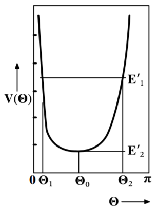
The effective potential \(V (\theta )\) is shown in Figure \(\PageIndex{2}\). It is clear that the motion of a symmetric top with effective energy \(E^{\prime}\) is confined to angles \(\theta_1 < \theta < \theta_2\). Note that the above result also is obtained if the Routhian is used, rather than the Lagrangian, as mentioned in chapter \(8.7\), and defined by equation \((8.6.8)\). That is, the Routhian can be written as
\[R(\theta , \dot{\theta} , p_{\phi} p_{\psi} )_{cyclic} = \dot{\phi} p_{ \phi} + \dot{\psi} p_{ \psi} − L = H (\phi , p_{\phi} , \psi , p_{\psi }) − L(\theta , \dot{\theta} )_{noncyclic} \\ = −\frac{1}{2} I_1 \dot{\theta}^2 + \frac{(p_{\phi }− p_{\psi} \cos \theta )^2}{ 2I_1 \sin^2 \theta} + \frac{p^2_{\psi}}{ 2I_3 } + Mgh \cos \theta \]
The Routhian \(R(\theta , \dot{\theta} , p_{\phi} p_{\psi} )_{cyclic}\) acts like a Hamiltonian for the \((\phi , p_{\phi} )\) and \((\psi , p_{\psi} )\) variables which are constants of motion, and thus are ignorable variables. The Routhian acts as the negative Lagrangian for the remaining variable \(\theta \), with rotational kinetic energy \(\frac{1} {2} I_1 \dot{\theta}^2\) and effective potential energy \(V_{eff}\)
\[V_{eff} = \frac{(p_{\phi} − p_{\psi} \cos \theta )^2}{2I_1 \sin^2 \theta } + \frac{p^2_{\psi}}{ I_3} + Mgh \cos \theta = V (\theta ) + \frac{p^2_{\psi}}{ I_3 }\notag\]
The equation of motion describing the system in the rotating frame is given by one Lagrange equation
\[\frac{d}{dt}(\frac{ \partial R_{cyclic} }{\partial \dot{\theta}} ) − \frac{\partial R_{cyclic}}{ \partial \theta} = 0 \notag\]
The negative sign of the Routhian cancels out when used in the Lagrange equation. Thus, in the rotating frame of reference, the system is reduced to a single degree of freedom, the nutation angle \(\theta\), with effective energy \(E^{\prime}\) given by equations \ref{13.186} - \ref{13.188}.
The motion of the symmetric top is simplest at the minimum value of the effective potential curve, where \(E^{\prime} = V_{\text{min}}\), at which the nutation \(\theta\) is restricted to a single value \(\theta = \theta_0\). The motion is a steady precession at a fixed angle of inclination, that is, the “sleeping top”. Solving for \((\frac{dV}{d\theta} )_{\theta =\theta_0} = 0\) gives that
\[p_{\phi} − p_{\psi} \cos \theta = \frac{p_{\psi} \sin^2 \theta_0 }{2 \cos \theta_0} \left[ 1 \pm \sqrt{ 1 − \frac{4MghI_1 \cos \theta_0 }{p^2_{\psi}}} \right]\]
If \(\theta_0 < \frac{\pi}{2}\), then to ensure that the solution is real requires a minimum value of the angular momentum on the body-fixed axis of \(p^2_{\psi} \geq 4MghI_1 \cos \theta_0\). If \(\theta_0 > \frac{\pi}{2}\) then there is no minimum angular momentum projection on the body-fixed axis. There are two possible solutions to the quadratic relation corresponding to either a slow or fast precessional frequency. Usually the slow precession is observed.
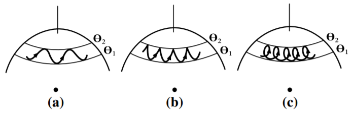
For the general case, where \(E^{\prime}_1 > V_{\text{min}}\), the nutation angle \(\theta\) between the space-fixed and body-fixed 3 axes varies in the range \(\theta_1 < \theta < \theta_2\). This axis exhibits a nodding variation which is called nutation. Figure \(\PageIndex{3}\) shows the projection of the body-fixed symmetry axis on the unit sphere in the space-fixed frame. Note that the observed nutation behavior depends on the relative sizes of \(p_{\phi}\) and \(p_{\psi} \cos \theta\). For certain values, the precession \(\dot{\phi}\) changes sign between the two limiting values of \(\theta\) producing a looping motion as shown in Figure \(\PageIndex{3c}\). Another condition is where the precession is zero for \(\theta_2\) producing a cusp at \(\theta_2\) as illustrated in Figure \(\PageIndex{3b}\). This behavior can be demonstrated using the gyroscope or the symmetric top.
Example \(\PageIndex{1}\): The Spinning "Jack"
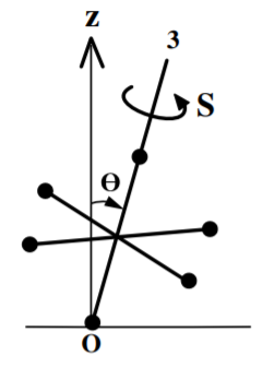
The game “Jacks” is played using metal Jacks, each of which comprises six equal masses \(m\) at the opposite ends of orthogonal axes of length \(l\). Consider one jack spinning around the body-fixed 3−axis with the lower mass at a fixed point on the ground, and with a steady precession around the space-fixed vertical axis \(z\) with angle \(\theta\) as shown. Assume that the body-fixed axes align with the arms of the jack.
The principal moments of inertia about one mass is given by the parallel axis theorem to be \(I_2 = I_1 = 4ml^2+6ml^2 = 10ml^2\) and \(I_3 = 4ml^2\).
In the rotating body-fixed frame the torque due to gravity has components
\[\mathbf{N} = \begin{pmatrix} 6mgl \sin \theta \sin\psi \\ 6mgl \sin \theta \cos \psi \\ 0 \end{pmatrix}\notag \]
and the components of the angular velocity are
\[\boldsymbol{\omega} = \begin{pmatrix} \dot{\phi} \sin \theta \sin\psi + \dot{\theta} \cos \psi \\ \dot{\phi} \sin \theta \cos \psi − \dot{\theta} \sin \\ \dot{\phi} \cos \theta + \dot{\psi} \end{pmatrix} \notag\]
Using Euler’s equations \((13.17.6)\) for the above components of \(N\) and \(\omega\) in the body-fixed frame, gives
\[10\dot{\omega}_1 − 6\omega_2\omega_3 = \frac{6g}{l} \sin \theta \sin \psi \label{a}\tag{a} \]
\[10\dot{\omega}_2 − 6\omega_1\omega_3 = \frac{6g}{l} \sin \theta \cos \psi \label{b}\tag{b}\]
\[ 4\dot{\omega}_3 = 0 \label{c}\tag{c}\]
Equation \ref{c} relates the spin about the 3 axis, the precession, and the angle to the vertical \(\theta\), that is
\[\omega_3 = \dot{\phi} \cos \theta + \dot{\psi} = \Omega \cos \theta + s = \text{ constant}\]
where \(\dot{\psi} \equiv s\) is the spin and \(\dot{\phi} \equiv \Omega\) is the precession angular velocity.
If the spin axis is nearly vertical, \(\theta \approx 0\) and thus \(\sin \theta \approx \theta\) and \(\cos \theta \approx 1\). Multiply Equation \ref{a} \(\times \sin\psi +\) \ref{b} \(\times \cos \psi\) and using the equations of the components of \(\omega\) gives
\[5\ddot{\theta} + \left( 2\Omega s − 3\Omega^2 − \frac{3g}{l} \right) \theta = 0 \notag\]
The bracket must be positive to have stable sinusoidal oscillations. That is, the spin angular velocity \(s\) required for the jack to spin about a stable vertical axis is given by.
\[s > \frac{3\Omega}{2} + \frac{3g}{2l \Omega}\notag\]
This example illustrates the conditions required for stable rotation of any axially-symmetric top.
Example \(\PageIndex{2}\): The Tippe Top
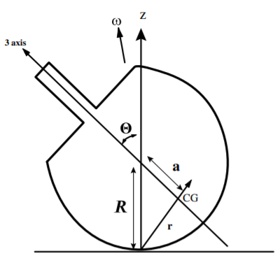
The Tippe Top comprises a section of a sphere, to which a short cylindrical rod is mounted on the planar section, as illustrated. When the Tippe Top is spun on a horizontal surface this top exhibits the perverse behavior of transitioning from rotation with the spherical head resting on the horizontal surface, to flipping over such that it rotates resting on its elongated cylindrical rod. The orientation of angular momentum remains roughly vertical as expected from conservation of angular momentum. This implies that the rotation with respect to the body-fixed axes must invert as the top inverts. The center of mass is raised when the top inverts; the additional potential energy is provided by a reduction in the rotational kinetic energy.
The Tippe Top behavior was first discovered in the 1890’s but adequate solutions of the equations of motion have only been developed since the 1950’s. Since the top precesses around the vertical axis, the point of contact is not on the symmetry axis of the top. Sliding friction between the surface of the spinning top and the horizontal surface provides a torque that causes the precession of the top to increase and eventually flip up onto the cylindrical peg. The Tippe Top is typical of many phenomena in physics where the underlying physics principle can be recognized but a detailed and rigorous solution can be complicated.
The system has five degrees of freedom, \(x,y\) which specify the location on the horizontal plane, plus the three Euler angles \((\varphi, \theta , \phi )\). The paper by Cohen[Coh77] explains the motion in terms of Euler angles using the laboratory to body-fixed transformation relation. It shows that friction plays a pivotal role in the motion contrary to some earlier claims. Ciocci and Langerock[Cio07] used the Routhian \(R_{cyclic}\) to reduce the number of degrees of freedom from 5 to 2, namely \(\theta\) which is the tilt angle, and \(\varphi^{\prime}\) which is the orientation of the tilt. This Routhian \(R_{cyclic}\) is a Lagrangian in two dimension that was used to derive the equations of motion via the Lagrange Euler equation
\[\begin{aligned} \frac{d}{dt}( \frac{ \partial R_{cyclic} }{\partial \dot{\theta} }) − \frac{\partial R_{cyclic} }{\partial \theta} = Q_{\theta} \\ \frac{d}{dt}( \frac{\partial R_{cyclic}}{ \partial \dot{\varphi}^{\prime}}) − \frac{\partial R_{cyclic}}{ \partial \varphi^{\prime}} = Q_{\varphi^{\prime}}\end{aligned}\]
where the \(Q_{\theta} \ Q_{\varphi^{\prime}}\) are generalized torques about the 2 angles that take into account the sliding frictional forces. This sophisticated Routhian reduction approach provides an exhaustive and refined solution for the Tippe Top and confirms that sliding friction plays a key role in the unusual behavior of the Tippe Top.