
5.16: Inserting a Dielectric into a Capacitor


( \newcommand{\kernel}{\mathrm{null}\,}\)
Suppose you start with two plates separated by a vacuum or by air, with a potential difference across the plates, and you then insert a dielectric material of permittivity ϵ0 between the plates. Does the intensity of the field change or does it stay the same? If the former, does it increase or decrease?
The answer to these questions depends
- on whether, by the field, you are referring to the E-field or the D-field;
- on whether the plates are isolated or if they are connected to the poles of a battery.
We shall start by supposing that the plates are isolated. See Figure V.20.
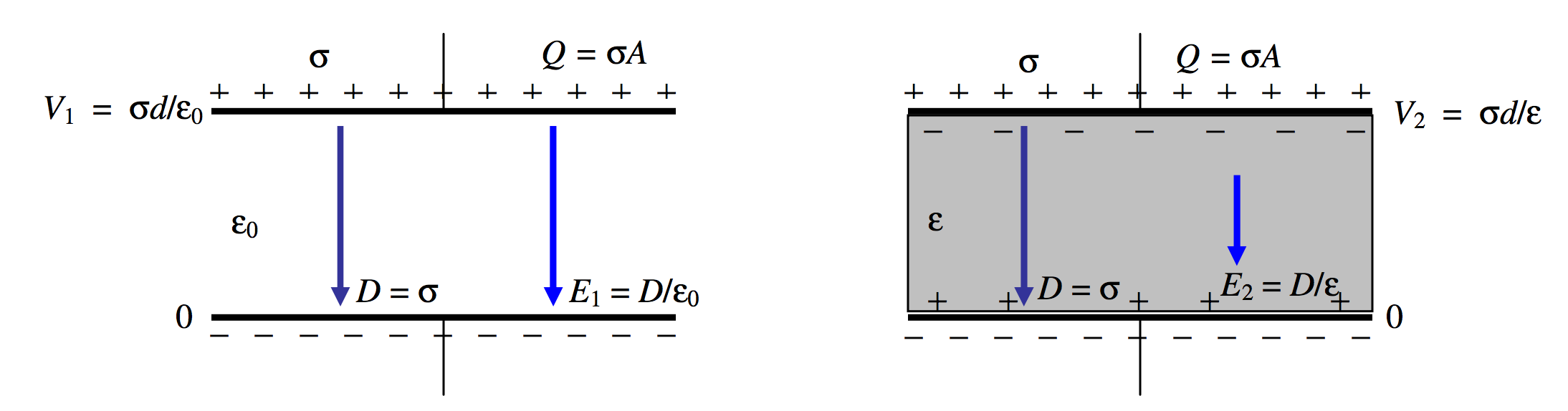
FIGURE V.20
Let Q be the charge on the plates, and σ the surface charge density. These are unaltered by the introduction of the dielectric. Gauss’s law provides that D=σ, so this, too, is unaltered by the introduction of the dielectric. The electric field was, initially, E1=D/ϵ0. After introduction of the dielectric, it is a little less, namely E1=D/ϵ.
Let us take the potential of the lower plate to be zero. Before introduction of the dielectric, the potential of the upper plate was V1=σd/ϵ0. After introduction of the dielectric, it is a little less, namely V1=σd/ϵ.
Why is the electric field E less after introduction of the dielectric material? It is because the dielectric material becomes polarized. We saw in Section 3.6 how matter may become polarized. Either molecules with pre-existing dipole moments align themselves with the imposed electric field, or, if they have no permanent dipole moment or if they cannot rotate, a dipole moment can be induced in the individual molecules. In any case, the effect of the alignment of all these molecular dipoles is that there is a slight surplus of positive charge on the surface of the dielectric material next to the negative plate, and a slight surplus of negative charge on the surface of the dielectric material next to the positive plate. This produces an electric field opposite to the direction of the imposed field, and thus the total electric field is somewhat reduced.
Before introduction of the dielectric material, the energy stored in the capacitor was 12QV1. After introduction of the material, it is 12QV2, which is a little bit less. Thus it will require work to remove the material from between the plates. The empty capacitor will tend to suck the material in, just as the charged rod in Chapter 1 attracted an uncharged pith ball.
Now let us suppose that the plates are connected to a battery. (Figure V.21)
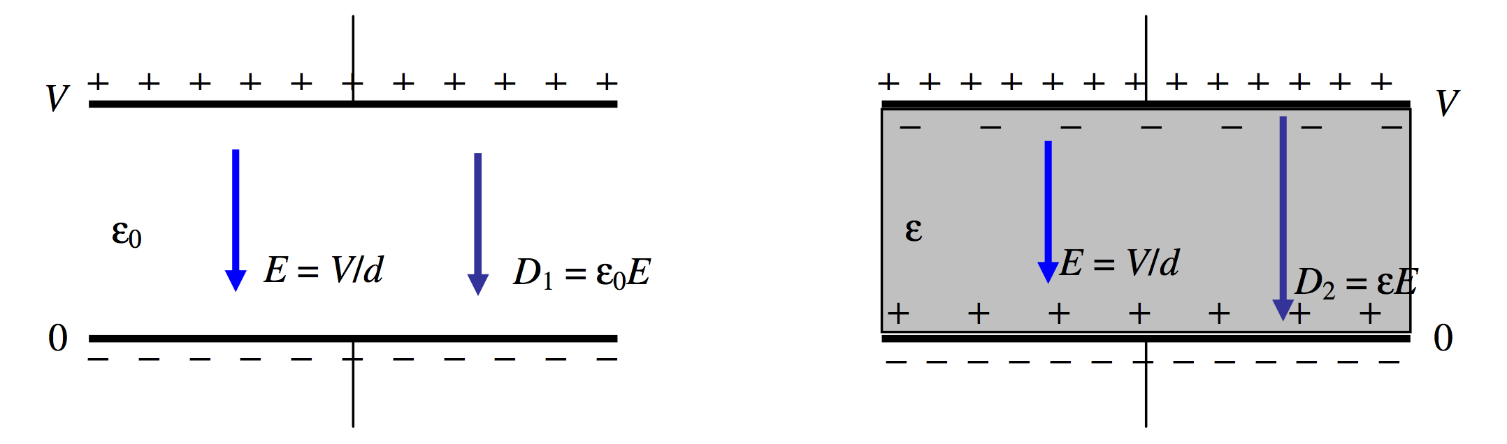
FIGURE V.21
This time the potential difference remains constant, and therefore so does the E-field, which is just V/d. But the D-field increases from ϵ0E to ϵE, and so, therefore, does the surface charge density on the plates. This extra charge comes from the battery.
The capacitance increases from ϵ0Ad to ϵAd and the charge stored on the plates increases from Q1=ϵ0AVd to Q2ϵAVd. The energy stored in the capacitor increases from 12Q1V to 12Q2V.
The energy supplied by the battery = the energy dumped into the capacitor + the energy required to suck the dielectric material into the capacitor:
(Q2−Q1)V=12(Q2−Q1)V+12(Q2−Q1)V.
You would have to do work to remove the material from the capacitor; half of the work you do would be the mechanical work performed in pulling the material out; the other half would be used in charging the battery.
In Section 5.15 I invented one type of battery charger. I am now going to make my fortune by inventing another type of battery charger.
Example 1.
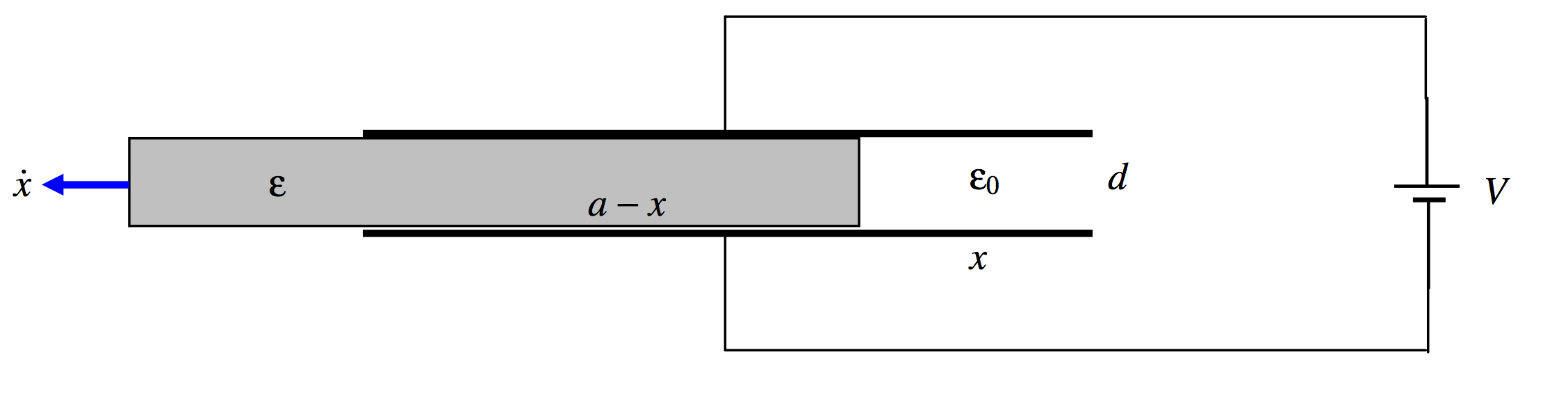
FIGURE V.22
A capacitor is formed of two square plates, each of dimensions a×a, separation d, connected to a battery. There is a dielectric medium of permittivity ϵ between the plates. I pull the dielectric medium out at speed ˙x. Calculate the current in the circuit as the battery is recharged.
Solution.
When I have moved a distance x, the capacitance is
ϵa(a−x)d+ϵ0axd=ϵa2−(ϵ−ϵ0)axd.
The charge held by the capacitor is then
Q=[ϵa2−(ϵ−ϵ0)axd]V.
If the dielectric is moved out at speed ˙x, the charge held by the capacitor will increase at a rate
˙Q=−(ϵ−ϵ0)a˙xVd.
(That’s negative, so Q decreases.) A current of this magnitude therefore flows clockwise around the circuit, into the battery. You should verify that the expression has the correct dimensions for current.
Example 2.
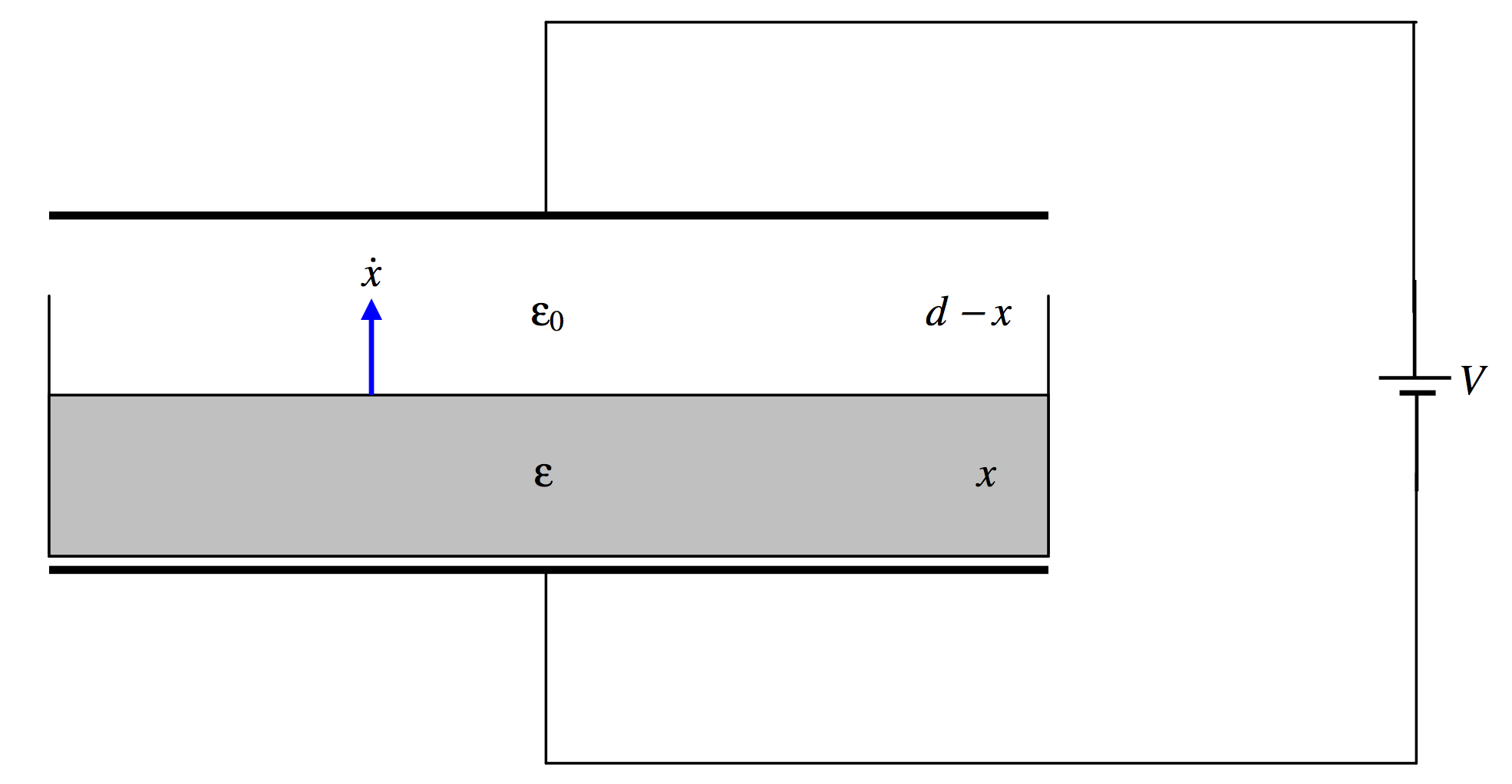
FIGURE V.23
A capacitor consists of two plates, each of area A, separated by a distance x, connected to a battery of EMF V. A cup rests on the lower plate. The cup is gradually filled with a nonconducting liquid of permittivity ϵ, the surface rising at a speed ˙x. Calculate the magnitude and direction of the current in the circuit.
It is easy to calculate that, when the liquid has a depth x, the capacitance of the capacitor is
C=ϵϵ0Aϵd−(ϵ−ϵ0)x
and the charge held by the capacitor is then
Q=ϵϵ0AVϵd−(ϵ−ϵ0)x.
If x is increasing at a rate ˙x, the rate at which Q, the charge on the capacitor, is increasing is
˙Q=ϵϵ0(ϵ−ϵ0)AV˙x[ϵd−(ϵ−ϵ0)x]2.
A current of this magnitude therefore flows in the circuit counterclockwise, draining the battery. This current increases monotonically from zero to ϵ(ϵ−ϵ0)AV˙xϵ0d2.