10.3: Lenz's Law
- Page ID
- 5475
\( \newcommand{\vecs}[1]{\overset { \scriptstyle \rightharpoonup} {\mathbf{#1}} } \)
\( \newcommand{\vecd}[1]{\overset{-\!-\!\rightharpoonup}{\vphantom{a}\smash {#1}}} \)
\( \newcommand{\dsum}{\displaystyle\sum\limits} \)
\( \newcommand{\dint}{\displaystyle\int\limits} \)
\( \newcommand{\dlim}{\displaystyle\lim\limits} \)
\( \newcommand{\id}{\mathrm{id}}\) \( \newcommand{\Span}{\mathrm{span}}\)
( \newcommand{\kernel}{\mathrm{null}\,}\) \( \newcommand{\range}{\mathrm{range}\,}\)
\( \newcommand{\RealPart}{\mathrm{Re}}\) \( \newcommand{\ImaginaryPart}{\mathrm{Im}}\)
\( \newcommand{\Argument}{\mathrm{Arg}}\) \( \newcommand{\norm}[1]{\| #1 \|}\)
\( \newcommand{\inner}[2]{\langle #1, #2 \rangle}\)
\( \newcommand{\Span}{\mathrm{span}}\)
\( \newcommand{\id}{\mathrm{id}}\)
\( \newcommand{\Span}{\mathrm{span}}\)
\( \newcommand{\kernel}{\mathrm{null}\,}\)
\( \newcommand{\range}{\mathrm{range}\,}\)
\( \newcommand{\RealPart}{\mathrm{Re}}\)
\( \newcommand{\ImaginaryPart}{\mathrm{Im}}\)
\( \newcommand{\Argument}{\mathrm{Arg}}\)
\( \newcommand{\norm}[1]{\| #1 \|}\)
\( \newcommand{\inner}[2]{\langle #1, #2 \rangle}\)
\( \newcommand{\Span}{\mathrm{span}}\) \( \newcommand{\AA}{\unicode[.8,0]{x212B}}\)
\( \newcommand{\vectorA}[1]{\vec{#1}} % arrow\)
\( \newcommand{\vectorAt}[1]{\vec{\text{#1}}} % arrow\)
\( \newcommand{\vectorB}[1]{\overset { \scriptstyle \rightharpoonup} {\mathbf{#1}} } \)
\( \newcommand{\vectorC}[1]{\textbf{#1}} \)
\( \newcommand{\vectorD}[1]{\overrightarrow{#1}} \)
\( \newcommand{\vectorDt}[1]{\overrightarrow{\text{#1}}} \)
\( \newcommand{\vectE}[1]{\overset{-\!-\!\rightharpoonup}{\vphantom{a}\smash{\mathbf {#1}}}} \)
\( \newcommand{\vecs}[1]{\overset { \scriptstyle \rightharpoonup} {\mathbf{#1}} } \)
\(\newcommand{\longvect}{\overrightarrow}\)
\( \newcommand{\vecd}[1]{\overset{-\!-\!\rightharpoonup}{\vphantom{a}\smash {#1}}} \)
\(\newcommand{\avec}{\mathbf a}\) \(\newcommand{\bvec}{\mathbf b}\) \(\newcommand{\cvec}{\mathbf c}\) \(\newcommand{\dvec}{\mathbf d}\) \(\newcommand{\dtil}{\widetilde{\mathbf d}}\) \(\newcommand{\evec}{\mathbf e}\) \(\newcommand{\fvec}{\mathbf f}\) \(\newcommand{\nvec}{\mathbf n}\) \(\newcommand{\pvec}{\mathbf p}\) \(\newcommand{\qvec}{\mathbf q}\) \(\newcommand{\svec}{\mathbf s}\) \(\newcommand{\tvec}{\mathbf t}\) \(\newcommand{\uvec}{\mathbf u}\) \(\newcommand{\vvec}{\mathbf v}\) \(\newcommand{\wvec}{\mathbf w}\) \(\newcommand{\xvec}{\mathbf x}\) \(\newcommand{\yvec}{\mathbf y}\) \(\newcommand{\zvec}{\mathbf z}\) \(\newcommand{\rvec}{\mathbf r}\) \(\newcommand{\mvec}{\mathbf m}\) \(\newcommand{\zerovec}{\mathbf 0}\) \(\newcommand{\onevec}{\mathbf 1}\) \(\newcommand{\real}{\mathbb R}\) \(\newcommand{\twovec}[2]{\left[\begin{array}{r}#1 \\ #2 \end{array}\right]}\) \(\newcommand{\ctwovec}[2]{\left[\begin{array}{c}#1 \\ #2 \end{array}\right]}\) \(\newcommand{\threevec}[3]{\left[\begin{array}{r}#1 \\ #2 \\ #3 \end{array}\right]}\) \(\newcommand{\cthreevec}[3]{\left[\begin{array}{c}#1 \\ #2 \\ #3 \end{array}\right]}\) \(\newcommand{\fourvec}[4]{\left[\begin{array}{r}#1 \\ #2 \\ #3 \\ #4 \end{array}\right]}\) \(\newcommand{\cfourvec}[4]{\left[\begin{array}{c}#1 \\ #2 \\ #3 \\ #4 \end{array}\right]}\) \(\newcommand{\fivevec}[5]{\left[\begin{array}{r}#1 \\ #2 \\ #3 \\ #4 \\ #5 \\ \end{array}\right]}\) \(\newcommand{\cfivevec}[5]{\left[\begin{array}{c}#1 \\ #2 \\ #3 \\ #4 \\ #5 \\ \end{array}\right]}\) \(\newcommand{\mattwo}[4]{\left[\begin{array}{rr}#1 \amp #2 \\ #3 \amp #4 \\ \end{array}\right]}\) \(\newcommand{\laspan}[1]{\text{Span}\{#1\}}\) \(\newcommand{\bcal}{\cal B}\) \(\newcommand{\ccal}{\cal C}\) \(\newcommand{\scal}{\cal S}\) \(\newcommand{\wcal}{\cal W}\) \(\newcommand{\ecal}{\cal E}\) \(\newcommand{\coords}[2]{\left\{#1\right\}_{#2}}\) \(\newcommand{\gray}[1]{\color{gray}{#1}}\) \(\newcommand{\lgray}[1]{\color{lightgray}{#1}}\) \(\newcommand{\rank}{\operatorname{rank}}\) \(\newcommand{\row}{\text{Row}}\) \(\newcommand{\col}{\text{Col}}\) \(\renewcommand{\row}{\text{Row}}\) \(\newcommand{\nul}{\text{Nul}}\) \(\newcommand{\var}{\text{Var}}\) \(\newcommand{\corr}{\text{corr}}\) \(\newcommand{\len}[1]{\left|#1\right|}\) \(\newcommand{\bbar}{\overline{\bvec}}\) \(\newcommand{\bhat}{\widehat{\bvec}}\) \(\newcommand{\bperp}{\bvec^\perp}\) \(\newcommand{\xhat}{\widehat{\xvec}}\) \(\newcommand{\vhat}{\widehat{\vvec}}\) \(\newcommand{\uhat}{\widehat{\uvec}}\) \(\newcommand{\what}{\widehat{\wvec}}\) \(\newcommand{\Sighat}{\widehat{\Sigma}}\) \(\newcommand{\lt}{<}\) \(\newcommand{\gt}{>}\) \(\newcommand{\amp}{&}\) \(\definecolor{fillinmathshade}{gray}{0.9}\)We can now address ourselves to the direction of the induced EMF. From our knowledge of the Lorentz force \(q \textbf{v}\times \textbf{B}\) we see that the current flows counterclockwise, and that this results in a force on the rod that is in the opposite direction to its motion. But, even if we did not know this law, or had forgotten the formula, or if we didn't understand a vector product, we could see that this must be so. For, suppose that we move the rod to the right, and that, as a consequence, there will be a force also the right. Then the rod moves faster, and the force to the right is greater, and the rod moves yet faster, and so on. The rod would accelerate indefinitely, for the expenditure of no work. No – this cannot be right. The direction of the induced EMF must be such as to oppose the change of flux that causes it. This is merely a consequence of conservation of energy, and it can be stated as Lenz's Law:
Lenz's Law
When an EMF is induced in a circuit as a result of changing magnetic flux through the circuit, the direction of the induced EMF is such as to oppose the change of flux that causes it.
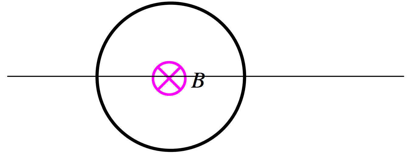
In our example of Section 10.2, we increased the magnetic flux through a circuit by increasing the area of the circuit. There are other ways of changing the flux through a circuit. For example, in Figure X.3, we have a circular wire and a magnetic field perpendicular to the plane of the circle, directed into the plane of the drawing.

\(\text{FIGURE X.3}\)
We could increase the magnetic flux through the coil by increasing the strength of the field rather than by increasing the area of the coil. The rate of increase of the flux would then be \(A\dot B\) rather than \(\dot A B\). We could imagine increasing \(B\), for example by moving a magnet closer to the coil, or by moving the coil into a region where the magnetic field was stronger; or, if the magnetic field is generated by an electromagnet somewhere, by increasing the current in the electromagnet. One way or another, we increase the strength of the field through the coil. An EMF is generated in the coil equal to the rate of change of magnetic flux, and consequently a current flows in the coil. In which direction does this induced current flow? It flows in such a direction as to oppose the increase in \(B\) that causes it. That is, the current flows counterclockwise in the coil. If this were not so, and the induced current were clockwise, this would still further increase the flux through the coil, and the current would increase further, and the flux would increase further, and so on. A runaway increase in the current and the field would result, and energy would not be conserved.
If we were in decrease the strength of the field through the coil, a current would flow clockwise in the coil – i.e. in such a sense as to tend to increase the field – i.e. to oppose the decrease in field that we are trying to impose. It may well occur to you at this stage that it is impossible to increase the current in a circuit instantaneously, and it takes a finite time to establish a new level of current. This is correct – a point to which we shall return later, when indeed we shall calculate just how long it does take.
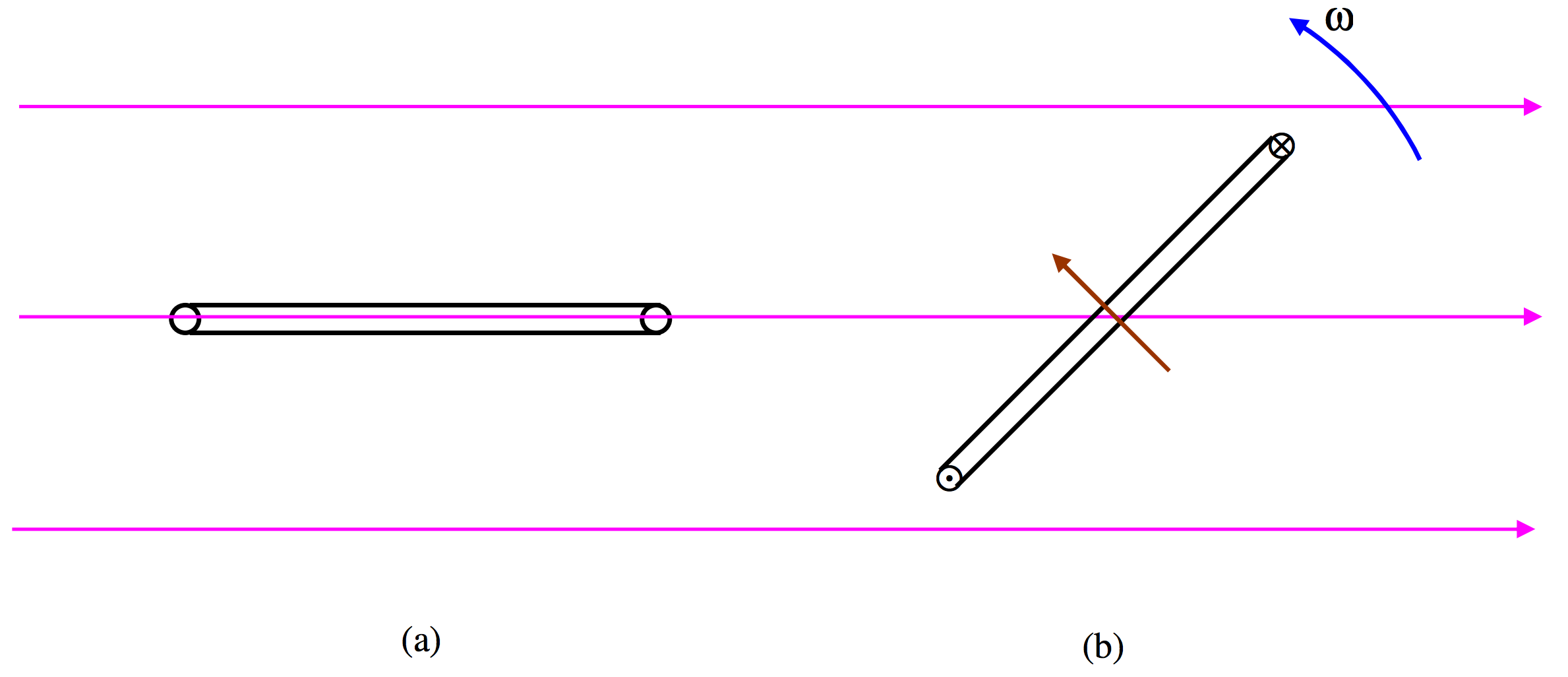
Another way in which we could change the magnetic flux through a coil would be to rotate the coil in a magnetic field. For example, in Figure X.4a, we see a magnetic field directed to the right, and a coil whose normal is perpendicular to the field. There is no magnetic flux through the coil. If we now rotate the coil, as in Figure X.4b, the flux through the coil will increase, an EMF will be induced in the coil, equal to the rate of increase of flux, and a current will flow. The current will flow in a direction such that the magnetic moment of the coil will be as shown, which will result in an opposition to our imposed rotation on the coil, and the current will flow in the direction indicated by the symbols \(\bigodot \text{ and }\bigotimes\).

\(\text{FIGURE X.4}\)
If the flux through a coil changes at a rate \(\dot \Phi_B\) and if the coil is not just a single turn but is made of \(N\) turns, the induced EMF will be \(\dot \Phi_B\) per turn, so that the induced EMF in the coil as a whole will be \(N\dot \Phi_B\).


