6.7: Fraunhofer Diffraction Revisited
- Page ID
- 57628
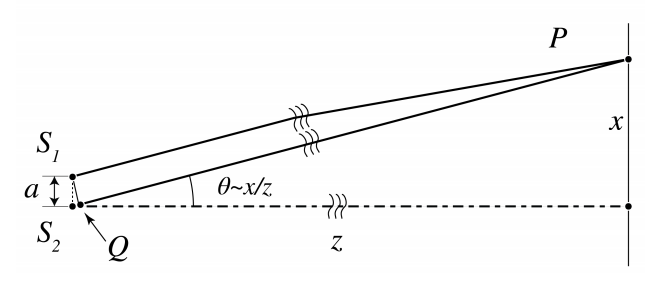
Fraunhofer diffraction patterns can qualitatively explained by considering directions in which destructive and constructive interference occurs. Consider two mutually coherent point sources \(S_{1}, S_{2}\) on the \(x\)-axis as shown in Figure \(\PageIndex{1}\). We assume that these point sources are in phase. On a screen at large distance \(z\) an interference pattern is observed. If the distance \(z\) of the screen is very large, the spherical wave fronts emitted by the point sources are almost plane at the screen. In point \(P\) on the screen at a distance \(x\) above the \(z\)-axis the optical path differences of the waves emitted by the two sources is approximately given by \(S_{2} Q=a \theta\), where \(\theta=x / z\) is assumed small. Hence constructive interference occurs for angles \(\theta\) such that \(S_{2} Q=m \lambda\) for some integer \(m\), i.e. when \[\theta=m \frac{\lambda}{a}, \quad \text { constructive interference. } \nonumber \]
Destructive interference occurs when the path length difference satisfies \(S_{2} Q=\lambda / 2+m \lambda\) for some integer \(m\), hence for angles \[\theta=(m+1 / 2) \frac{\lambda}{a} \quad \text { destructive interference. } \nonumber \]
If the point sources have the same strength, their fields perfectly cancel for these angles.
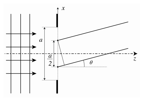
Now consider a slit as shown in Figure \(\PageIndex{2}\) which is illuminated by a perpendicular incident plane wave. By the Huygens-Fresnel principle, the field at a screen far from the slit is the sum of the fields of point sources in the aperture. Since the slit is illuminated by a plane wave at perpendicular incidence, all point sources are in phase and have equal strength. Divide the slit in two equal halves as shown in Figure \(\PageIndex{2}\). The point sources in the slit can be arranged into pairs, of which one point source is in the upper half of the slit and the other is at the equivalent position (at distance \(a / 2\) from the other point source) in the lower half of the slit. Let \(\theta\) be an angle for which the two point sources of a pair cancel each other i.e. \[\theta=(m+1 / 2) \frac{\lambda}{a / 2}=(1+2 m) \frac{\lambda}{a}, \nonumber \] since the distance between the point sources is \(a / 2\). By translating the pair of point sources through the slits, it follows that both half slits perfectly cancel each other for these angles.
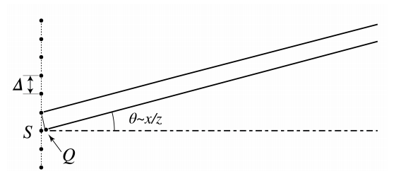
Next consider a diffraction grating with period \(\Delta\). It follows from Figure \(\PageIndex{3}\) that there will be constructive interference between adjacent periods, and hence for all periods, for angles for which the distance \(S Q\) in Fig \(\PageIndex{3}\) is a multiple of the wavelength, i.e. for \[\theta=m \frac{\lambda}{\Delta} \text {, } \nonumber \] which corresponds to the direction of the diffraction orders. For other angles the phases of the fields of the different periods differ widely and therefore the fields almost cancel at these angles.
This explains that for a diffraction grating consisting of many periods, the far field intensity is high only in particular directions, depending on the wavelength and the period of the grating.