4.3: Astigmatism
- Page ID
- 7089
\( \newcommand{\vecs}[1]{\overset { \scriptstyle \rightharpoonup} {\mathbf{#1}} } \)
\( \newcommand{\vecd}[1]{\overset{-\!-\!\rightharpoonup}{\vphantom{a}\smash {#1}}} \)
\( \newcommand{\dsum}{\displaystyle\sum\limits} \)
\( \newcommand{\dint}{\displaystyle\int\limits} \)
\( \newcommand{\dlim}{\displaystyle\lim\limits} \)
\( \newcommand{\id}{\mathrm{id}}\) \( \newcommand{\Span}{\mathrm{span}}\)
( \newcommand{\kernel}{\mathrm{null}\,}\) \( \newcommand{\range}{\mathrm{range}\,}\)
\( \newcommand{\RealPart}{\mathrm{Re}}\) \( \newcommand{\ImaginaryPart}{\mathrm{Im}}\)
\( \newcommand{\Argument}{\mathrm{Arg}}\) \( \newcommand{\norm}[1]{\| #1 \|}\)
\( \newcommand{\inner}[2]{\langle #1, #2 \rangle}\)
\( \newcommand{\Span}{\mathrm{span}}\)
\( \newcommand{\id}{\mathrm{id}}\)
\( \newcommand{\Span}{\mathrm{span}}\)
\( \newcommand{\kernel}{\mathrm{null}\,}\)
\( \newcommand{\range}{\mathrm{range}\,}\)
\( \newcommand{\RealPart}{\mathrm{Re}}\)
\( \newcommand{\ImaginaryPart}{\mathrm{Im}}\)
\( \newcommand{\Argument}{\mathrm{Arg}}\)
\( \newcommand{\norm}[1]{\| #1 \|}\)
\( \newcommand{\inner}[2]{\langle #1, #2 \rangle}\)
\( \newcommand{\Span}{\mathrm{span}}\) \( \newcommand{\AA}{\unicode[.8,0]{x212B}}\)
\( \newcommand{\vectorA}[1]{\vec{#1}} % arrow\)
\( \newcommand{\vectorAt}[1]{\vec{\text{#1}}} % arrow\)
\( \newcommand{\vectorB}[1]{\overset { \scriptstyle \rightharpoonup} {\mathbf{#1}} } \)
\( \newcommand{\vectorC}[1]{\textbf{#1}} \)
\( \newcommand{\vectorD}[1]{\overrightarrow{#1}} \)
\( \newcommand{\vectorDt}[1]{\overrightarrow{\text{#1}}} \)
\( \newcommand{\vectE}[1]{\overset{-\!-\!\rightharpoonup}{\vphantom{a}\smash{\mathbf {#1}}}} \)
\( \newcommand{\vecs}[1]{\overset { \scriptstyle \rightharpoonup} {\mathbf{#1}} } \)
\(\newcommand{\longvect}{\overrightarrow}\)
\( \newcommand{\vecd}[1]{\overset{-\!-\!\rightharpoonup}{\vphantom{a}\smash {#1}}} \)
\(\newcommand{\avec}{\mathbf a}\) \(\newcommand{\bvec}{\mathbf b}\) \(\newcommand{\cvec}{\mathbf c}\) \(\newcommand{\dvec}{\mathbf d}\) \(\newcommand{\dtil}{\widetilde{\mathbf d}}\) \(\newcommand{\evec}{\mathbf e}\) \(\newcommand{\fvec}{\mathbf f}\) \(\newcommand{\nvec}{\mathbf n}\) \(\newcommand{\pvec}{\mathbf p}\) \(\newcommand{\qvec}{\mathbf q}\) \(\newcommand{\svec}{\mathbf s}\) \(\newcommand{\tvec}{\mathbf t}\) \(\newcommand{\uvec}{\mathbf u}\) \(\newcommand{\vvec}{\mathbf v}\) \(\newcommand{\wvec}{\mathbf w}\) \(\newcommand{\xvec}{\mathbf x}\) \(\newcommand{\yvec}{\mathbf y}\) \(\newcommand{\zvec}{\mathbf z}\) \(\newcommand{\rvec}{\mathbf r}\) \(\newcommand{\mvec}{\mathbf m}\) \(\newcommand{\zerovec}{\mathbf 0}\) \(\newcommand{\onevec}{\mathbf 1}\) \(\newcommand{\real}{\mathbb R}\) \(\newcommand{\twovec}[2]{\left[\begin{array}{r}#1 \\ #2 \end{array}\right]}\) \(\newcommand{\ctwovec}[2]{\left[\begin{array}{c}#1 \\ #2 \end{array}\right]}\) \(\newcommand{\threevec}[3]{\left[\begin{array}{r}#1 \\ #2 \\ #3 \end{array}\right]}\) \(\newcommand{\cthreevec}[3]{\left[\begin{array}{c}#1 \\ #2 \\ #3 \end{array}\right]}\) \(\newcommand{\fourvec}[4]{\left[\begin{array}{r}#1 \\ #2 \\ #3 \\ #4 \end{array}\right]}\) \(\newcommand{\cfourvec}[4]{\left[\begin{array}{c}#1 \\ #2 \\ #3 \\ #4 \end{array}\right]}\) \(\newcommand{\fivevec}[5]{\left[\begin{array}{r}#1 \\ #2 \\ #3 \\ #4 \\ #5 \\ \end{array}\right]}\) \(\newcommand{\cfivevec}[5]{\left[\begin{array}{c}#1 \\ #2 \\ #3 \\ #4 \\ #5 \\ \end{array}\right]}\) \(\newcommand{\mattwo}[4]{\left[\begin{array}{rr}#1 \amp #2 \\ #3 \amp #4 \\ \end{array}\right]}\) \(\newcommand{\laspan}[1]{\text{Span}\{#1\}}\) \(\newcommand{\bcal}{\cal B}\) \(\newcommand{\ccal}{\cal C}\) \(\newcommand{\scal}{\cal S}\) \(\newcommand{\wcal}{\cal W}\) \(\newcommand{\ecal}{\cal E}\) \(\newcommand{\coords}[2]{\left\{#1\right\}_{#2}}\) \(\newcommand{\gray}[1]{\color{gray}{#1}}\) \(\newcommand{\lgray}[1]{\color{lightgray}{#1}}\) \(\newcommand{\rank}{\operatorname{rank}}\) \(\newcommand{\row}{\text{Row}}\) \(\newcommand{\col}{\text{Col}}\) \(\renewcommand{\row}{\text{Row}}\) \(\newcommand{\nul}{\text{Nul}}\) \(\newcommand{\var}{\text{Var}}\) \(\newcommand{\corr}{\text{corr}}\) \(\newcommand{\len}[1]{\left|#1\right|}\) \(\newcommand{\bbar}{\overline{\bvec}}\) \(\newcommand{\bhat}{\widehat{\bvec}}\) \(\newcommand{\bperp}{\bvec^\perp}\) \(\newcommand{\xhat}{\widehat{\xvec}}\) \(\newcommand{\vhat}{\widehat{\vvec}}\) \(\newcommand{\uhat}{\widehat{\uvec}}\) \(\newcommand{\what}{\widehat{\wvec}}\) \(\newcommand{\Sighat}{\widehat{\Sigma}}\) \(\newcommand{\lt}{<}\) \(\newcommand{\gt}{>}\) \(\newcommand{\amp}{&}\) \(\definecolor{fillinmathshade}{gray}{0.9}\)In Greek, stigma means a mark - in particular the mark made by the prick of a pointed instrument. An ideal optical instrument produces an image of a point source, which is also a point. If the image is not a point, then it is astigmatic. However, the use of the word astigmatic to describe an image of a point source that is not also a point is restricted to the kind of optical aberration described in this section.
The easiest way to understand the phenomenon of astigmatism is to imagine a lens (or mirror) whose surfaces are not exactly spherical but for which the radius of curvature (and hence focal length) in one plane is different from the radius of curvature in a plane at right angles to the first.

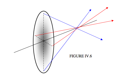
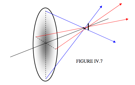
This is going to stretch my poor artistic abilities to the limit. The ellipse is intended to represent a lens seen somewhat from behind, at an angle. The black line is its optical axis. The lens is supposed to be illuminated from the left with a beam of light parallel to the optical axis. I have drawn two transmitted rays in the vertical plane by means of two blue arrows converging on to the optical axis at some distance from the lens. I have drawn two transmitted rays in the horizontal plane by means of two red arrows converging on to the optical axis at a slightly greater distance from the lens. (The colours of the arrows are not intended to means different colours of light. We’ll suppose that the light is all monochromatic.) Evidently the rays from different points around the circumference of the lens come to a confused mess on the optical axis; the image is decidedly astigmatic. In fact at one point on the optical axis, a line image is formed; a little further along the axis, another line image, at right angles to the first, is formed. In Figure IV.7, I repeat Figure IV.6, but I add these two line images.

As you move along the optical axis, the image changes from a horizontal line to a vertical line in a sequence that looks something like this:

Somewhere about half way between the two linear images is the “circle of least confusion”.
I have explained the aberration of astigmatism by supposing that the lens has a different focal length in one plane than in the other. This may be the easiest way for an introductory explanation of the aberration. However, in practice it is unlikely that a lens has different focal lengths in two orthogonal planes; indeed it would be quite difficult to make such a lens.
In most cases astigmatism is caused, as we shall see, by using a perfectly good lens or mirror off-axis.
If you look at a star through a telescope, and if you move the eyepiece in and out as you look through it, you may see the star image going through a series of astigmatic images such as illustrated above. This is not usually caused by a bad lens, but is caused if the object glass (in a refracting telescope) or lens (in a reflecting telescope) is crooked in its cell, so that you are using it off-axis. Indeed, doing this little test is a good way of telling whether the object glass or the mirror is crooked in its cell.
Although different radii of curvature in different planes is not the usual cause of astigmatism, there is an exception - namely, the human eye. If the radii of curvature of the cornea, or of the lens, is different in different planes, then the image on the retina will be astigmatic even on-axis.
We saw in Chapter 1 that refraction at a plane surface produces spherical aberration. It is not always appreciated that refraction at a plane surface produces astigmatism when the surface is viewed at an angle. If you visit an aquarium and look into glass side of a tank at an angle, you will see that the fish look a little blurred because of this astigmatism.
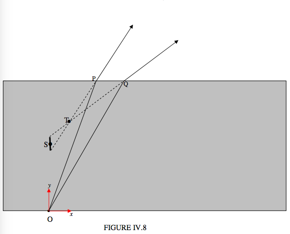
In Figure IV.8 I have drawn two rays from a point O at the bottom of a glass block, making angles of 20° and 30° with the normal to the upper surface. With a refractive index of 1.6 the angles that the emerging rays make with the normal are 33° and 53°. I refer to the plane of the paper (or your computer screen) as the tangential plane. A vertical plane perpendicular to the plane of the paper is the sagittal plane. You will see that the two rays in the tangential plane diverge, after refraction, from a point T in the tangential plane. If we take the height of the glass block to be 1, we can calculate that the \((x, y)\) coordinates of the point T in the tangential plane are (0.145, 0.666).
To anticipate, the image at T is not a point; rather, it is a short horizontal line in the sagittal plane, perpendicular to the plane of the paper.

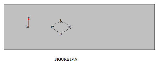
Now let’s look at the glass block from above:

I have drawn (accurately, I hope, after some calculation) the ellipse where the cone of light coming from O intersects the upper surface of the block. The point P and Q are in the tangential plane, and light emerging from P and Q appears to diverge from T. The points R and U are in the sagittal plane. Tracing the rays OR and OU after emergence from the block doesn’t look very easy, but it will probably be agreed that they do not diverge from T, as the rays in the tangential plane did. Indeed, after further thought, you’ll probably see that the rays OR and OU after emergence will be diverging from a point S on the \(y\)-axis; that is to say, directly above O.
For reference, the coordinates of the several points on the drawing, if my calculations are correct, are:
O: (0.000 000 000 , 0.000 000 000 , 0.000 000 000)
P: (0.363 970 234 , 1.000 000 000 , 0.000 000 000)
Q: (0.577 350 269 , 1.000 000 000 , 0.000 000 000)
R: (0.470 660 252 , 1.000 000 000 , 0.069 344 256)
U: (0.470 660 252 , 1.000 000 000 , −0.069 344 256)
T: (0.145 831 216 , 0.666 360 298 , 0.000 000 000)
S: (0.000 000 000 , 0.497 301 940 , 0.000 000 000)
The angle of incidence of the ray at R is 25.442 358 40 degrees to the normal, and the angle of refraction is 43.421 850 83 degrees.
The net result of this is that there is a short linear “image” at T perpendicular to the tangential plane, and a short linear “image” at S perpendicular to the sagittal plane, and, somewhere in between, there is a circle of least confusion. One way of looking at the situation is to recognize that the wavefront of the emergent cone is nonspherical - its radii of curvature are different in the tangential and sagittal planes.
Thus refraction at a plane surface results in both spherical aberration and astigmatism. Refraction through a glass prism, as in a prism spectrograph, also produces astigmatism, and it can be shown that the astigmatism is least when the light passes through the prism symmetrically in the position of minimum deviation. This is one reason why prism spectrographs are normally used in the position of minimum deviation.
We have seen that a lens does not produce a point image of a point object on the axis of the lens, but the image is subject to spherical aberration. The spherical aberration is small if the aperture of the lens is small compared with its focal length and object and image distances, so that the angles that the various rays make with the optic axis are small enough that one can make the approximation \(\sin \theta \approx \tan \theta \approx \theta\), and is small also if the shape of the lens is suitably designed as in the example in Section 4.2. For a point object on the axis, the image is free of astigmatism (presuming that the radii of curvature of the lens in the tangential and sagittal planes are equal). However, for a point object off-axis, in which the light passes through the lens at an oblique angle, the refracted cone gives rise to an astigmatic image in just the same way as for oblique refraction at a plane surface. This there will be a line “image” normal to the tangential plane, and, at a different distance, there will be another line normal to the sagittal plane , and a circle of least confusion between them. The further off-axis the object, the greater will be the distance between the tangential and sagittal lines. (The distance will be zero for a point object on axis.) Unlike the case for spherical aberration, the amount of astigmatism (the distance between T and S) is not greatly improved by changing the shape of the lens, and a third lens component is often used to correct for the astigmatism.
We mentioned, however, that astigmatism in the eye is generally caused by different tangential and sagittal curvatures of the cornea, and it is evident on axis as well as off axis. It may be corrected by a single lens, which is designed to have different tangential and sagittal curvatures. Such lenses are not easy to make, and they are generally fairly expensive


