
11.5: Rotational dynamics for a solid object


- Last updated
- Mar 28, 2024
- Save as PDF
( \newcommand{\kernel}{\mathrm{null}\,}\)
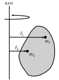
We now consider the rotational dynamics for a solid object about a specific axis of rotation. Just as we did in Chapter 10, we model a solid object as a system made of many particles of mass mi. Because all of the points in a solid must move in unison, they all rotate about an axis of rotation instead of a point. We describe the position of each particle i by a vector →ri that is perpendicular to the axis of rotation and goes from the axis to the corresponding particle, as shown in Figure 11.5.1.
We wish to model the motion of the object as it rotates about a specific axis. Thus, when considering the net torque on any particle i, we only consider the component of the particle’s net torque that is parallel to the axis of rotation (that component of torque that comes from forces that are in the plane perpendicular to the rotation axis).
We can write the rotational version of Newton’s Second Law for particle, i, with mass mi, and position vector →ri relative to the rotation axis:
∑k→τik=→τneti=mir2i→αi
where →τik is the k-th torque on particle i. →τneti is the net torque on the particle about the axis of rotation and →αi is the particle’s angular acceleration about that axis.
We can divide the torques exerted on a particle into internal and external torques. Internal torques are those exerted by another particle in the system, whereas external torques are exerted by something external to the system. If particle 1 exerts a torque →τ on particle 2, particle 2 will exert an equal and opposite torque, −→τ on particle 1.
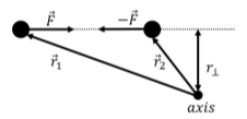
Indeed, consider the two particles that exert an equal and opposite force (Newton’s Third Law), →F, on each other, and an arbitrary point/axis of rotation, as illustrated in Figure 11.5.2. The torque on particle 1 from the force exerted by particle 2 will have the same magnitude as the torque on particle 2 from the force by particle 1. This is because both forces have the same magnitude and they are co-linear, which results in them having the same lever arm. The torque vector from each force will be in opposite directions, because the forces are in opposite direction. Newton’s Third Law thus also holds for torques.
We can sum together the equations for each particle i:
→τnet1+→τnet2+→τnet3+…=m1r21→α1+m2r22→α2+m3r23→α3+…∑i→τneti=∑imir2i→αi
where the sum over all of the torques exerted on each particle will be equal to the net external torque exerted on all of the particles, since the sum of the internal torques, →τinti, will be zero:
∑i→τneti=∑i→τinti+∑i→τexti=∑i→τexti=→τext
where →τext is the net external torque on the system.
All of the particles are part of the same rigid body, and cannot move relative to each other. Furthermore, they must all move around circles that are centered about the axis of rotation and in a plane perpendicular to that axis. They must thus all have the same angular acceleration1, →αi=→α1=→α2=⋯=→α. We can thus factor the angular acceleration, →α, out of the sum.
We can thus write Newton’s Second Law for rotational dynamics of a solid object as:
∑i→τneti=∑imir2i→αi∴→τext=(∑imir2i)→α
The term in parentheses describes how the various masses are distributed relative to the axis of rotation. The term in parenthesis is called the moment of inertia of the object, and usually denoted with the letter, I:
I=∑imir2i
The moment of inertia is a property of the object relative to a specific axis of rotation. Re-writing Newton’s Second Law for the rotational dynamics of solid objects using the moment of inertia:
→τext=I→α
The net torque exerted on an object in the direction of the axis of rotation is thus equal to its moment of inertia about that axis multiplied by its angular acceleration about that axis. In other words, the moment of inertia describes how the object will resist rotational motion given a net torque. An object with a smaller moment of inertia will have a larger angular acceleration for a given torque. Again, this is analogous to the linear case, where the acceleration of an object given a net force is determined by its inertial mass.
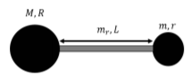
Two small point masses, m, are connected by a mass-less rod of length L to form a dumbbell, as illustrated in Figure 11.5.3. A net force of magnitude F is exerted on each mass, in opposite directions, as illustrated in the Figure.
- What is the linear acceleration of the center of mass of the dumbbell?
- What is the angular acceleration of the dumbbell relative to an axis that goes through its center of mass and is perpendicular to the page?
- What is the angular acceleration of the dumbbell relative to an axis that goes through one of the masses and is perpendicular to the page?
Solution
We model the dumbbell as a rigid body made of two point masses held at a fixed distance.
a. The linear acceleration of the center of mass must be zero, because the net force on the dumbbell is zero. However, just because the center of mass does not move does not mean that all parts of the dumbbell are immobile.
b. First, we calculate the angular acceleration relative to an axis that is perpendicular the page and goes through the center of mass. The center of mass is located midway between the two masses, as illustrated in Figure 11.5.4. We also define a coordinate system as shown, such that the z axis is out of the page.
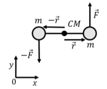
The vector from the axis of rotation to each mass will have the same magnitude, r, but different directions. The net external torque on the dumbbell relative to the axis that goes through the center of mass, →τext, which is equal to the sum of the torques from each force:
→τext=→r×→F+(−→r)×(−→F)=2(→r×→F)=2(rˆx×Fˆy)=2rF(ˆx׈y)=2rFˆz=LFˆz
where we used the fact that 2r=L. The net torque is thus non zero and in the positive z direction; the dumbbell will have an angular acceleration that is parallel to the net torque, and thus will accelerate in the counter-clockwise direction.
The moment of inertia of the dumbbell relative to the axis through the center of mass is given by:
I=∑imir2i=mr2+mr2=2mr2=12mL2
Using Newton’s Second Law for rotational dynamics, we find the angular acceleration to be:
→τext=I→αLFˆz=12mL2→α∴→α=2FmLˆz
Because the center of mass is fixed (the sum of the forces is zero), the two ends of the dumbbell will rotate about an axis that goes through the center of mass. This is a feature of all situations in which the net force on an object is zero and the net torque about an axis that goes through the center of mass is non-zero.
c. Let us now calculate the angular acceleration of the dumbbell about an axis that goes through one of the masses, as illustrated in Figure 11.5.5.
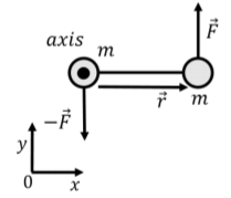
We first calculate the net torque on the dumbbell. The vector that goes from the axis of rotation to the force exerted on the mass that coincides with the rotation axis is zero. Thus, only the force exerted on the mass that is not at the rotation axis contributes to the net torque:
→τext=→r×→F=LFˆz
The moment of inertia of the dumbbell about this axis is:
I=∑imir2i=m(0)2+m(r2)=mL2
which is larger than it was about the center of mass. Again, the angular acceleration is found using Newton’s Second Law for rotational dynamics:
→τext=I→αLFˆz=mL2→α∴→α=FmLˆz
We find that the angular acceleration is smaller about an axis that goes through one of the mass than it is about an axis through the center of mass. Because the center of mass of the dumbbell is fixed, we can only think of the dumbbell as instantaneously rotating about one of its ends; that is, the motion of the dumbbell will not be such that one mass rotates about the other; this is only true instantaneously.
Discussion
This simple example illustrates several key features about rotational dynamics:
- If the sum of the forces on an object is zero, it does not mean that the entire object is stationary; it only implies that the center of mass is stationary (or rather, moving with a constant velocity, but we can always choose to model the system in a frame of reference where the center of mass is stationary).
- If the sum of the forces on an object is zero, and the sum of the external torques is non-zero, the object will rotate about an axis that goes through the center of mass. That is, all points on the object will move along circles that are centered on an axis that goes through the center of mass.
- We can model the rotating object about any axis that we choose. In general, the net external torque and the moment of inertia will depend on the choice of axis, as will the resulting angular acceleration.
- When determining the motion of the center of mass, we can draw a free-body diagram, and the location of where the forces are exerted do not matter.
- When determining how the object rotates, we cannot use a free-body diagram, because it matters where the forces are applied (as the torque from a given force depends on the location where the force is applied relative to the axis of rotation).
Footnotes
1. They will have different linear accelerations, but the angular acceleration (and angular velocity) will be the same for all particles if they are moving in unison.