
11.10: Sample problems and solutions


- Last updated
- Mar 28, 2024
- Save as PDF
( \newcommand{\kernel}{\mathrm{null}\,}\)
Calculate the moment of inertia of a uniform disk of mass M and radius R, rotated about an axis that goes through its center and is perpendicular to the disk.
- Answer
-
We need to split up the disk into mass elements, dm, that we can sum together to obtain the moment of inertia of the disk. We can choose a ring of radius r and radial thickness dr for the shape of our mass element, as depicted in Figure 11.10.1.

Figure 11.10.1: A mass element, dm, in the shape of a ring of radius r and radial thickness dr. We can define a surface mass density, σ, equal to the mass per unit area of the disk:
σ=MπR2
The mass of the ring shaped element is thus given by:
dm=σ2πrdr
where 2πrdr is the area of the mass element. You can imagine unfolding the mass element into a rectangle of height dr and of length 2πr to obtain its area. Now that we have expressed the mass element in terms of r, we can proceed to calculate the moment of inertia of the disk.
We know from Example 11.6.1, that the infinitesimal moment of inertia, dI, of a ring of radius r and infinitesimal mass, dm, about its axis of symmetry is given by:
dI=dmr2
The moment of inertia of the disk, is found by summing the moments of inertia of the infinitesimal rings:
I=∫dI=∫dmr2=∫R0σ2πrdrr2=2πσ∫R0r3dr=2πσ14R4=2π(MπR2)14R4=12MR2
where we removed the surface mass density by expressing it in term of the total mass and radius of the disk.
Discussion
The moment of inertia of a disk of mass M and radius R is half of that of a ring of radius R and mass M. It is thus easier to rotate the disk than the ring.
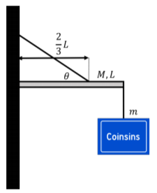
A sign holder is built by attaching a bar of mass M and length L to a wall using a hinge that allows the bar to rotate in the vertical plane. The sign of mass m is attached to the end of the bar that is opposite from the wall. The bar is held up by a rope that is attached to the wall on one end and to the bar on the other end, two thirds of the length of the bar from the wall, as illustrated in Figure 11.10.2. The rope makes an angle θ with respect to the horizontal bar. Find the tension in the rope and the magnitude of the force exerted by the hinge onto the bar.
- Answer
-
The whole system does not move and so it is in static equilibrium. In order to determine the forces exerted on the bar by the rope and the hinge, we model the bar as being in static equilibrium. The forces exerted on the bar are:
- →Fg, the weight of the bar, with magnitude Mg, exerted at the bar’s center of mass.
- →Fm, a downwards forced exerted by the sign at the end of the bar, with magnitude mg.
- →T, a force of tension exerted by the rope at a distance 2/3L from the wall.
- →R, a force exerted by the hinge on the bar at the end next to the wall1. We expect that the force from the hinge will have both a horizontal component, Rx, and a vertical component, Ry, in order for the net force on the bar to be zero.
The forces are illustrated in Figure 11.10.3 along with our choice of coordinate system (and the z axis, not shown, points out of the page).
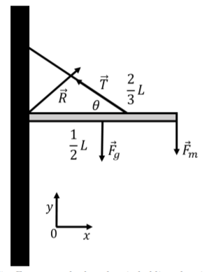
Figure 11.10.3: Forces on the bar that is holding the sign of mass m. We start by writing out the x and y components of Newton’s Second Law (with zero acceleration):
∑Fx=Rx−Tcosθ=0∑Fy=Ry+Tsinθ−Mg−mg=0
We can choose the axis about which to calculate the torques. Since all of the forces are in the xy plane, we choose to calculate the torques about an axis parallel to the z axis that goes through the hinge on the wall. The force from the hinge, →R, will thus result in a torque of zero (since it has a lever arm of zero). The torque from each force about the hinge is given by:
→τM=→rM×→Fg=(L2ˆx)×(−Mgˆy)=−MgL2ˆz→τT=→rT×→T=(L3ˆx)×(−Tcosθˆx+Tsinθˆy)=TsinθL3ˆz→τm=→rm×→Fm=(Lˆx)×(−mgˆy)=−mgLˆz
The sum of the torques in the z direction must be zero for static equilibrium, which allows us to determine the magnitude of the force of tension:
∑τz=τMz+τTz+τmz=0−MgL2+TsinθL3−mgL=0−Mg12+Tsinθ13−mg=0∴T=3gsinθ(m+M2)
Using the x and y components of Newton’s Second Law, we can now use the tension to determine the x and y components of the force exerted by the hinge:
Rx=Tcosθ=3gtanθ(m+M2)Ry=(M+m)g−Tsinθ=(M+m)g−3g(m+M2)=−(2m+M2)g
We find that the y component of the force from the hinge is in the negative y direction, so our diagram in Figure 11.10.3 is wrong! If you removed the hinge on the wall and instead held that end of the bar with your hand, you would feel that the end of the bar is trying to go into the wall and upwards, as the bar tries to rotate with the opposite end moving downwards due to the weight of the sign. You would have to push in the positive x and negative y direction to keep the bar from moving.
Discussion
In this example, we saw that we needed to use both the sum of the forces and the sum of the torques in order to determine the forces on the bar.
Footnotes
1. We chose the letter R for “Reaction”, as this is the force of reaction from the hinge as the bar pushes against the hinge.