
20.3: Applying Kirchhoff’s rule to model circuits
- Page ID
- 19516
In this section, we show how to model a circuit using Kirchhoff’s rules. In general, one can consider a circuit to be fully modeled if one can determine the current in each segment of the circuit. We will show how one can apply the same procedure to model any circuit that contains batteries and resistors. The procedure is as follows:
- Make a good diagram of the circuit.
- Simplify any resistors that can easily be combined into effective resistors (in series or in parallel).
- Make a new diagram with the effective resistors, showing battery arrows, and labeling all of the nodes so that loops can easily be described.
- Make a guess for the directions of the current in each segment.
- Write the junction rule equations.
- Write the loop equations.
- This will lead to \(N\) independent equations that one can solve for the \(N\) different currents in the circuit.
- Once you have determined all of the currents, if some of them are negative numbers, switch the direction of those currents in the diagram (they will be negative if you guessed the direction incorrectly).
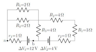
We will illustrate the procedure on the circuit shown in Figure \(\PageIndex{1}\), for which we would like to know the current through each resistor and each battery. The circuit contains 5 resistors (\(R_1\)-\(R_5\)), 2 real batteries (with ideal voltages \(\Delta V_1\) and \(\Delta V_2\)), and 2 additional resistors to model the internal resistances of the real batteries (\(r_1\), \(r_2\))
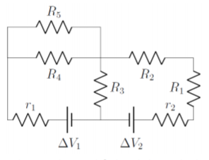
How many different currents are in the circuit shown in Figure \(\PageIndex{1}\)?
- 3
- 4
- 5
- 6
- Answer
Simplifying the resistors (step 2): In this circuit, resistors \(r_2\), \(R_1\) and \(R_2\) are in series, so that they can be combined into an effective resistor, \(R_6\):
\[\begin{aligned} R_6=r_2+R_1+R_2\end{aligned}\]
With this simplification, we obtain the circuit illustrated in Figure \(\PageIndex{2}\)
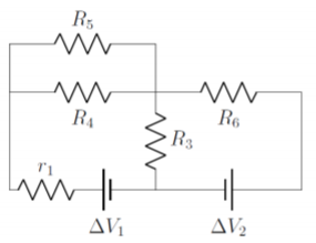
Next, we note that resistors \(R_4\) and \(R_5\) are in parallel and can be easily combined into a resistor, \(R_7\):
\[\begin{aligned} R_7=\frac{R_4R_5}{R_4+R_5}\end{aligned}\]
which leads to the circuit illustrated in Figure \(\PageIndex{3}\).
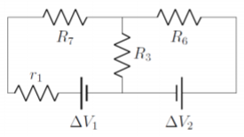
Finally, we note that \(r_1\) and \(R_7\) are in series and can be combined into an effective resistor, \(R_8\):
\[\begin{aligned} R_8=r_1+R_7=r_1+\frac{R_4R_5}{R_4+R_5}\end{aligned}\]
leading to the simplified circuit illustrated in Figure \(\PageIndex{2}\), which we have labeled with nodes and battery labels.
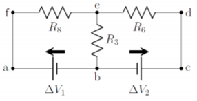
Guessing the directions of the currents (step 4): Before we can write the equations from Kirchhoff’s rules, we need to label the currents in the circuit diagram. In general, it is not always obvious in which way the currents will go, so we make a guess that we can fix later if we guessed wrong.
In order to guess the current directions, choose one point on the circuit and move along a segment. Label the current in that segment and continue moving through the circuit, splitting up the current when a junction is encountered. Make sure to only have one current per segment. We guess the currents as follows, referring to Figure \(\PageIndex{5}\):
- We start at point \(a\) and move upwards to point \(f\). We will call the current in that segment, \(I_1\).
- Since there is no junction, the current \(I_1\) continues through the resistor \(R_8\) to point \(e\).
- There is a junction at point \(e\), so we split the current \(I_1\) into currents \(I_2\) (towards point \(d\)), and \(I_3\) (downwards to point \(b\)).
- We follow current \(I_2\) first; \(I_2\) flows from \(e\) to \(d\), then down to \(c\), through the battery \(\Delta V_2\), and to point \(b\), where there is again junction.
- We follow current \(I_3\), which just flows down to the junction at point \(b\), where it “meets up” with current \(I_2\).
- Currents \(I_2\) and \(I_3\) both flow into the junction at point \(b\), and the current flowing out of the junction, through the battery \(\Delta V_1\), and towards point \(a\) is, again, \(I_1\), since this current then flows up to point \(f\).
- All segments of wire have a labeled current, so we are done guessing currents.
You can proceed in an analogous way for any circuit. The final circuit, with currents labeled, is shown in Figure \(\PageIndex{5}\):
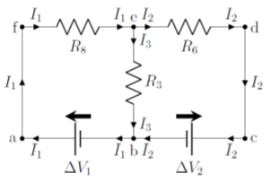
We can now proceed with using Kirchhoff’s rules to solve for the values of the currents in the circuit. It is useful to note that there are 3 unknown currents in this circuit; we thus hope that Kirchhoff’s rules will give us 3 independent equations.
Applying the junction rule (step 5): In the circuit from Figure \(\PageIndex{5}\), there are two junctions (at points \(b\) and \(e\)), so we will get two equations from the junction rule. To apply the junction rule, the sum of the currents coming into the junction must be equal to the currents going out of the junction:
\[\begin{aligned} \text{incoming currents}&=\text{outgoing currents}&\\[4pt] I_2+I_3 &= I_1 \quad &\text{(junction $b$)}\\[4pt] I_1 &= I_2+I_3 \quad &\text{(junction $e$)}\\[4pt]\end{aligned}\]
Note that the two equations are not independent (in fact, they are the same). It is generally the case that if there \(N\) junctions, one will obtain less than \(N\) independent equations (usually, \(N-1\) equations will be independent). In this case, the two junctions only gave us one equation.
Applying the loop rule (step 6): This circuit contains 3 different loops: \(abcdefa\), \(abefa\), and \(bcdeb\), which will lead to 3 equations from the loop rule. We expect that these equations will not be independent, since this would lead to 4 equations and 3 unknowns when combined with the junction rule equation. Let us start with the loop \(abcdefa\):
- From \(a\) to \(b\), we trace through the battery in the opposite direction from the battery arrow: \(-\Delta V_1\).
- From \(b\) to \(c\), we trace through the battery in the same direction as the battery arrow: \(+\Delta V_2\).
- From \(c\) through \(d\) and through to \(e\) we go through the resistor \(R_6\) in the opposite direction from the current, \(I_2\), in that resistor: \(+I_2R_6\).
- From \(e\) to \(f\), we go through the go through the resistor \(R_8\) in the opposite direction from the current, \(I_1\), in that resistor: \(+I_1R_8\).
- And we are back at the starting point, so the sum of the above terms is equal to zero.
which gives the equation:
\[\begin{aligned} -\Delta V_1+\Delta V_2+I_2R_6+I_1R_8=0\quad\text{(loop abcdefa)}\end{aligned}\]
Similarly, for the loop \(abefa\), we obtain:
\[\begin{aligned} -\Delta V_1+I_3R_3+I_1R_8=0\quad\text{(loop abefa)}\end{aligned}\]
and for loop \(bcdeb\):
\[\begin{aligned} \Delta V_2+I_2R_6-I_3R_3=0\quad\text{(loop bcdeb)}\end{aligned}\]
Although it appears that we have obtained 3 additional equations, only two of these are independent. For example, if you sum the second and third equations (loops \(abefa\), and \(bcdeb\)), you simply obtain the first equation (loop \(abcdefa\)). In general, if there are \(N\) different loops, one will obtain less than \(N\) independent equations (usually \(N-1\) independent equations, as we did here).
At this point, after choosing one of the junction equations, and two of the loop equations, we have 3 independent equations that we can solve for the 3 unknown currents1:
\[\begin{aligned} I_1 &= I_2+I_3 \quad &\text{(junction $e$)}\\[4pt] -\Delta V_1+\Delta V_2+I_2R_6+I_1R_8&=0\quad&\text{(loop abcdefa)}\\[4pt] -\Delta V_1+I_3R_3+I_1R_8&=0\quad&\text{(loop abefa)}\end{aligned}\]
It is only a matter of some simple math to solve for the 3 unknowns from these 3 equations (which we carry out in the example below).
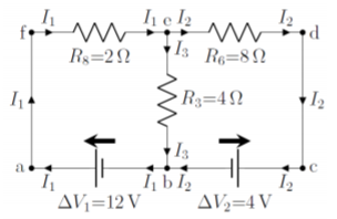
Referring to the circuit in Figure \(\PageIndex{6}\), what is the voltage across the real terminal of the battery with ideal voltage \(\Delta V_1\) (the voltage between points \(a\) and \(b\))? What is the current through resistor \(R_5\)?
Solution
Since this circuit is the same that we just analyzed, we know that it can be simplified into the circuit shown in Figure \(\PageIndex{7}\), with resistors:
\[\begin{aligned} R_6&=r_2+R_1+R_2=(1\Omega)+(3\Omega)+(4\Omega)=8\Omega\\[4pt] R_8&=r_1+\frac{R_4R_5}{R_4+R_5}=(1\Omega)+\frac{(2\Omega)(2\Omega)}{(2\Omega)+(2\Omega)}=2\Omega\end{aligned}\]
From above, we know that this leads to the following three equations:
\[\begin{aligned} I_1 &= I_2+I_3 \quad &\text{(junction $e$)}\\[4pt] -\Delta V_1+\Delta V_2+I_2R_6+I_1R_8&=0\quad&\text{(loop abcdefa)}\\[4pt] -\Delta V_1+I_3R_3+I_1R_8&=0\quad&\text{(loop abefa)}\end{aligned}\]
In order to solve these types of equations, it is usually convenient to place the battery voltages on the right hand side, and the resistor voltages on the left hand side. Although it is generally bad practice to fill numbers into the equations before solving them, it is almost always a good idea when solving the \(N\) equations for the \(N\) currents. Furthermore, in order to make the equations legible, it is also useful to not write in the units (which is very bad practice in general!). Thus, filling in the values for the resistors and the battery voltages, moving the voltages to the right hand side, we obtain the following system of equations:
\[\begin{aligned} I_1-I_2-I_3&=0 \quad &\text{(junction $e$)}\\[4pt] 2I_1+8I_2&=8 \quad&\text{(loop abcdefa)}\\[4pt] 2I_1+4I_3&=12 \quad&\text{(loop abefa)}\end{aligned}\]
Subtracting the second equation from the third equation (to eliminate \(I_1\)):
\[\begin{aligned} 4I_3-8I_2&=4\\[4pt] \therefore I_3&=1+2I_2\end{aligned}\]
Substituting this into the junction equation:
\[\begin{aligned} I_1-I_2-I_3&=0\\[4pt] I_1-I_2-1-2I_2&=0\\[4pt] \therefore I_2=\frac{1}{3}(I_1-1)\end{aligned}\]
Finally, substituting this into the equation from loop \(abcdefa\), allows us to determine \(I_1\) and the other two currents:
\[\begin{aligned} 2I_1+8I_2&=8\\[4pt] 2I_1+8\left(\frac{1}{3}(I_1-1) \right)&=8\\[4pt] \therefore I_1&=\frac{16}{7}=2.29\text{A}\\[4pt] \therefore I_2&=\frac{1}{3}(I_1-1)=0.43\text{A}\\[4pt] \therefore I_3&=1+2I_2=1.86\text{A}\\[4pt]\end{aligned}\]
In this case, the currents are all positive, so the diagram in Figure \(\PageIndex{7}\) is correct and we do not need to reverse the direction of any of the currents.
We can now determine the potential difference across the real terminals of the battery \(\Delta V_1\). The current through the battery is \(I_1=2.29\text{A}\), which cause a voltage drop, \(\Delta V_{r1}\), across its internal resistance, \(r_1\) of:
\[\begin{aligned} \Delta V_{r1}=I_1r_1=(2.29\text{A})(1\Omega)=2.29\text{V}\end{aligned}\]
The voltage across the real terminals of the battery is then:
\[\begin{aligned} \Delta V_{real}=\Delta V_1-\Delta V_{r1}=(12\text{V})-(2.29\text{V})=9.7\text{V}\end{aligned}\]
The current through the resistor \(R_5\) (Figure \(\PageIndex{6}\)) requires a little more thought, since we calculated the current, \(I_1\) through the effective resistor \(R_8\), which we must now “break apart”. Figure \(\PageIndex{8}\) shows the components of \(R_8\).
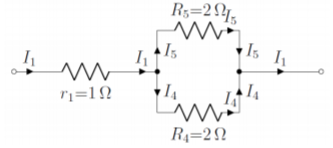
The current \(I_1\), that goes through the \(\Delta V_1\) battery also goes through the \(r_1\) internal resistance of the battery. That current then splits up into currents, \(I_4\) and \(I_5\), to go through the resistors \(R_4\) and \(R_5\). Although it should be obvious that half of \(I_1\) will go through each resistor (since these are equal), we can determine this from applying Kirchhoff’s rules to the combination of resistors in Figure \(\PageIndex{8}\):
\[\begin{aligned} I_1&=I_4+I_5 \quad&\text{(junction)}\\[4pt] I_5R_5-I_4R_4&=0\quad&\text{(clockwise loop)}\end{aligned}\]
From the loop equation, we have:
\[\begin{aligned} I_5=\frac{R_4}{R_5}I_4=I_4\end{aligned}\]
since \(R_4=R_5=2\Omega\). Since \(I_4=I_5\), the junction equation gives:
\[\begin{aligned} I_5=\frac{1}{2}I_1=1.15\text{A}\end{aligned}\]
By solving for \(I_4\) and \(I_5\), we have now determined all of the currents through all of the segments of the original circuit in Figure \(\PageIndex{6}\).
Discussion
In this example, we showed how one can use a simplified circuit to solve the current through the effective resistors in the simplified circuit. Once those currents are known, we showed that it is straightforward to determine the currents through individual resistors that have been combined into effective resistors.
Solving a circuit can be daunting, especially if the diagram is drawn in an unfamiliar way. While the circuits in this chapter are designed to be as easy to read as possible, many circuits are much more strange. For example, here is a circuit which you may come across:
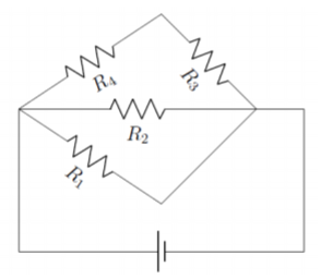
The circuit in Figure \(\PageIndex{9}\) May look like it is a difficult circuit to solve, but the diagram can be re-drawn to reveal the simplicity of the circuit:
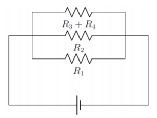
What used to be a strange kite shape is now just a parallel circuit, which can be further simplified by calculating the effective resistance:
\[\begin{aligned} R_{eff} &= (R_1^{-1}+R_2^{-1}+(R_3+R_4)^{-1})^{-1}\end{aligned}\]
Which gives a series circuit with only one resistor:
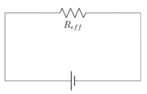
Circuits can be drawn in many unique or potentially confusing ways, but knowing how to read the circuit and re-draw it can help make the diagram more legible and the circuit easier to solve.
Footnotes
1. The 3 unknowns do not necessarily have to be the currents, and could be any combination of the currents, battery voltage and resistors. As long as there at most 3 unknown quantities, this circuit can be solved.