
20.4: Measuring current and voltage
- Page ID
- 19517
\( \newcommand{\vecs}[1]{\overset { \scriptstyle \rightharpoonup} {\mathbf{#1}} } \)
\( \newcommand{\vecd}[1]{\overset{-\!-\!\rightharpoonup}{\vphantom{a}\smash {#1}}} \)
\( \newcommand{\dsum}{\displaystyle\sum\limits} \)
\( \newcommand{\dint}{\displaystyle\int\limits} \)
\( \newcommand{\dlim}{\displaystyle\lim\limits} \)
\( \newcommand{\id}{\mathrm{id}}\) \( \newcommand{\Span}{\mathrm{span}}\)
( \newcommand{\kernel}{\mathrm{null}\,}\) \( \newcommand{\range}{\mathrm{range}\,}\)
\( \newcommand{\RealPart}{\mathrm{Re}}\) \( \newcommand{\ImaginaryPart}{\mathrm{Im}}\)
\( \newcommand{\Argument}{\mathrm{Arg}}\) \( \newcommand{\norm}[1]{\| #1 \|}\)
\( \newcommand{\inner}[2]{\langle #1, #2 \rangle}\)
\( \newcommand{\Span}{\mathrm{span}}\)
\( \newcommand{\id}{\mathrm{id}}\)
\( \newcommand{\Span}{\mathrm{span}}\)
\( \newcommand{\kernel}{\mathrm{null}\,}\)
\( \newcommand{\range}{\mathrm{range}\,}\)
\( \newcommand{\RealPart}{\mathrm{Re}}\)
\( \newcommand{\ImaginaryPart}{\mathrm{Im}}\)
\( \newcommand{\Argument}{\mathrm{Arg}}\)
\( \newcommand{\norm}[1]{\| #1 \|}\)
\( \newcommand{\inner}[2]{\langle #1, #2 \rangle}\)
\( \newcommand{\Span}{\mathrm{span}}\) \( \newcommand{\AA}{\unicode[.8,0]{x212B}}\)
\( \newcommand{\vectorA}[1]{\vec{#1}} % arrow\)
\( \newcommand{\vectorAt}[1]{\vec{\text{#1}}} % arrow\)
\( \newcommand{\vectorB}[1]{\overset { \scriptstyle \rightharpoonup} {\mathbf{#1}} } \)
\( \newcommand{\vectorC}[1]{\textbf{#1}} \)
\( \newcommand{\vectorD}[1]{\overrightarrow{#1}} \)
\( \newcommand{\vectorDt}[1]{\overrightarrow{\text{#1}}} \)
\( \newcommand{\vectE}[1]{\overset{-\!-\!\rightharpoonup}{\vphantom{a}\smash{\mathbf {#1}}}} \)
\( \newcommand{\vecs}[1]{\overset { \scriptstyle \rightharpoonup} {\mathbf{#1}} } \)
\(\newcommand{\longvect}{\overrightarrow}\)
\( \newcommand{\vecd}[1]{\overset{-\!-\!\rightharpoonup}{\vphantom{a}\smash {#1}}} \)
\(\newcommand{\avec}{\mathbf a}\) \(\newcommand{\bvec}{\mathbf b}\) \(\newcommand{\cvec}{\mathbf c}\) \(\newcommand{\dvec}{\mathbf d}\) \(\newcommand{\dtil}{\widetilde{\mathbf d}}\) \(\newcommand{\evec}{\mathbf e}\) \(\newcommand{\fvec}{\mathbf f}\) \(\newcommand{\nvec}{\mathbf n}\) \(\newcommand{\pvec}{\mathbf p}\) \(\newcommand{\qvec}{\mathbf q}\) \(\newcommand{\svec}{\mathbf s}\) \(\newcommand{\tvec}{\mathbf t}\) \(\newcommand{\uvec}{\mathbf u}\) \(\newcommand{\vvec}{\mathbf v}\) \(\newcommand{\wvec}{\mathbf w}\) \(\newcommand{\xvec}{\mathbf x}\) \(\newcommand{\yvec}{\mathbf y}\) \(\newcommand{\zvec}{\mathbf z}\) \(\newcommand{\rvec}{\mathbf r}\) \(\newcommand{\mvec}{\mathbf m}\) \(\newcommand{\zerovec}{\mathbf 0}\) \(\newcommand{\onevec}{\mathbf 1}\) \(\newcommand{\real}{\mathbb R}\) \(\newcommand{\twovec}[2]{\left[\begin{array}{r}#1 \\ #2 \end{array}\right]}\) \(\newcommand{\ctwovec}[2]{\left[\begin{array}{c}#1 \\ #2 \end{array}\right]}\) \(\newcommand{\threevec}[3]{\left[\begin{array}{r}#1 \\ #2 \\ #3 \end{array}\right]}\) \(\newcommand{\cthreevec}[3]{\left[\begin{array}{c}#1 \\ #2 \\ #3 \end{array}\right]}\) \(\newcommand{\fourvec}[4]{\left[\begin{array}{r}#1 \\ #2 \\ #3 \\ #4 \end{array}\right]}\) \(\newcommand{\cfourvec}[4]{\left[\begin{array}{c}#1 \\ #2 \\ #3 \\ #4 \end{array}\right]}\) \(\newcommand{\fivevec}[5]{\left[\begin{array}{r}#1 \\ #2 \\ #3 \\ #4 \\ #5 \\ \end{array}\right]}\) \(\newcommand{\cfivevec}[5]{\left[\begin{array}{c}#1 \\ #2 \\ #3 \\ #4 \\ #5 \\ \end{array}\right]}\) \(\newcommand{\mattwo}[4]{\left[\begin{array}{rr}#1 \amp #2 \\ #3 \amp #4 \\ \end{array}\right]}\) \(\newcommand{\laspan}[1]{\text{Span}\{#1\}}\) \(\newcommand{\bcal}{\cal B}\) \(\newcommand{\ccal}{\cal C}\) \(\newcommand{\scal}{\cal S}\) \(\newcommand{\wcal}{\cal W}\) \(\newcommand{\ecal}{\cal E}\) \(\newcommand{\coords}[2]{\left\{#1\right\}_{#2}}\) \(\newcommand{\gray}[1]{\color{gray}{#1}}\) \(\newcommand{\lgray}[1]{\color{lightgray}{#1}}\) \(\newcommand{\rank}{\operatorname{rank}}\) \(\newcommand{\row}{\text{Row}}\) \(\newcommand{\col}{\text{Col}}\) \(\renewcommand{\row}{\text{Row}}\) \(\newcommand{\nul}{\text{Nul}}\) \(\newcommand{\var}{\text{Var}}\) \(\newcommand{\corr}{\text{corr}}\) \(\newcommand{\len}[1]{\left|#1\right|}\) \(\newcommand{\bbar}{\overline{\bvec}}\) \(\newcommand{\bhat}{\widehat{\bvec}}\) \(\newcommand{\bperp}{\bvec^\perp}\) \(\newcommand{\xhat}{\widehat{\xvec}}\) \(\newcommand{\vhat}{\widehat{\vvec}}\) \(\newcommand{\uhat}{\widehat{\uvec}}\) \(\newcommand{\what}{\widehat{\wvec}}\) \(\newcommand{\Sighat}{\widehat{\Sigma}}\) \(\newcommand{\lt}{<}\) \(\newcommand{\gt}{>}\) \(\newcommand{\amp}{&}\) \(\definecolor{fillinmathshade}{gray}{0.9}\)In this section, we describe how one can build devices to measure current and voltage. A device that measures current is called an “ammeter” and a device that measured voltage is called a “voltmeter”. Nowadays, these are usually found within the same physical device (a “multimeter”), which can also measure resistance (by measuring voltage and current, resistance can easily determined). We will limit our description to the design of simple analogue ammeters and voltmeters.
As we will see in Chapter 21, it is straightforward to build a device that can measure very small amounts of current, by running the current through a coil in a magnetic field so that the coil can deflect a needle that indicates the amount of current. Such a device is called a “galvanometer” and is usually limited to measuring very small current (of order ). In this section, we describe how one can use a galvanometer in order to build ammeters to measure large currents, and voltmeters.
The ammeter
An ammeter is built by placing a galvanometer in parallel with a “shunt” resistor, \(R_s\). The shunt resistor is a small resistor that “shunts” (deflects) the current away from the galvanometer, so that most of the current goes through the shunt resistor. This is illustrated in Figure \(\PageIndex{1}\), which shows the galvanometer (circle with the \(G\) inside), the internal resistance of the galvanometer, \(R_G\), and the shunt resistor, \(R_S\). The actual ammeter would be contained in a box and have two connectors (shown as \(A\) and \(B\) in the figure).
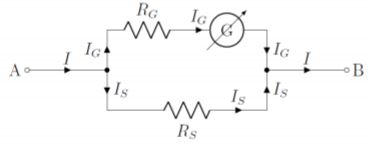
By modeling the ammeter, we can determine the total current, \(I\), that we would like to measure using the known values of the resistors and the current, \(I_G\), measured by the galvanometer. Considering any of the two junctions, and a clockwise loop, we have:
\[\begin{aligned} I&=I_G+I_S \quad&\text{(junction)}\\[4pt] I_GR_G-I_SR_S&=0\quad&\text{(clockwise loop)}\\[4pt] \therefore I_S&=\frac{R_G}{R_S}I_G\\[4pt] \therefore I &= I_G+_S=\left(1+\frac{R_G}{R_S}\right) R_G\end{aligned}\]
which allows us to determine the current, \(I\), from the current, \(I_G\), measured by the galvanometer. We also see that most of the current goes through the shunt (since \(R_S\) is chosen to be smaller than \(R_G\)). The ammeter, will have a total resistance, \(R_A\), given by:
\[\begin{aligned} R_A=\frac{R_GR_S}{R_G+R_S}\end{aligned}\]
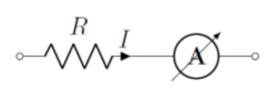
In order to measure the current through a specific segment of a circuit, an ammeter must be placed in series with that segment (so that the current that we want to measure will pass through the ammeter). Figure \(\PageIndex{2}\) shows how to connect an ammeter (circle with the letter \(A\)) in order to measure the current through a resistor, \(R\).
The voltmeter
A voltmeter is constructed by placing a large resistor, \(R_V\), in series with a galvanomenter (that has internal resistance \(R_G\)), as illustrated in Figure \(\PageIndex{3}\). The voltmeter is designed to measure the potential difference between the terminals of the voltmeter (labeled \(A\) and \(B\) in the Figure).
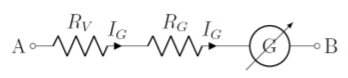
Given the values of the resistors, and the current measured by the galvanometer, one can easily determine the potential difference between points \(A\) and \(B\), since the current measured by the galvanometer goes directly through each resistor:
\[\begin{aligned} \Delta V = V_B-V_A=-I_G(R_V+R_G)\end{aligned}\]
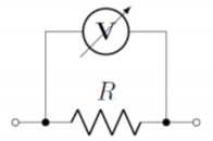
In order to measure a potential difference across a component, the voltmeter must be placed in parallel with the component. Figure \(\PageIndex{4}\) shows how to connect a voltmeter (circle with the letter \(V\)) in order to measure the voltage across a resistor, \(R\).
When using an ammeter or a voltmeter, you will notice that these usually have buttons or dials to choose the range of currents or voltages to be measured. All the dial does is change the value of the shunt or series resistor in order to maintain a given maximum current through the galvanometer. An ohmmeter, to measure resistance, is simply an ammeter with a built-in fixed potential difference (so that by measuring current across a known potential difference, the resistance of the component can be determined).
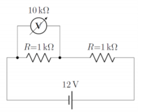
Two resistors with a resistance of \(1\text{k}\Omega\) are placed in series with a \(12\text{V}\) battery. A voltmeter with a total resistance of \(R_V=10\text{k}\Omega\) is used to measure the voltage across one of the resistors. What reading does the voltmeter show?
Solution
Since the two resistors have the same resistance, and are in series with the battery, when no voltmeter is connected, the voltage across either resistor is easily shown to be \(6\text{V}\). However, by connecting the voltmeter across one of the resistors, we modify the circuit, and we should expect the voltage that is read to be different than \(6\text{V}\) (can you tell if it will be larger or smaller?). The circuit, with the voltmeter connected is shown in Figure \(\PageIndex{5}\).
We can model this circuit quite easily by combining the voltmeter (modeled as a resistor) in parallel with one of the resistors:
\[\begin{aligned} R_{eff}=\frac{R_VR}{R_V+R}=\frac{(10\text{k}\Omega)(1\text{k}\Omega)}{(10\text{k}\Omega)+(1\text{k}\Omega)}=\frac{10}{11}\text{k}\Omega=0.91\text{k}\Omega\end{aligned}\]
The sum of the voltage drops across the effective resistor and the other resistor must equal the potential difference across the battery (Kirchhoff’s loop rule):
\[\begin{aligned} R_{eff}I+RI&=\Delta V\\[4pt] \therefore I &= \frac{\Delta V}{R_{eff}+R}=\frac{(12\text{V})}{(0.91\text{k}\Omega)+(1\text{k}\Omega)}=6.29\times 10^{-3}\text{A}\end{aligned}\]
The voltage drop across the effective resistor is the same as the reading on the voltmeter:
\[\begin{aligned} \Delta V_{voltmeter}=IR_{eff}=(6.29\times 10^{-3}\text{A})(0.91\text{k}\Omega)=5.7\text{V}\end{aligned}\]
and the voltmeter reads a smaller voltage than there would be without the voltmeter.
Discussion
In this example, we saw that by using a voltmeter to measure a voltage in a circuit, we actually disturb the circuit. By placing the voltmeter in parallel with one resistor, we created an effective resistor with a resistance that is lower than the resistance of either the voltmeter or the resistor. This lowered the total resistance of the circuit, which increased the current. A larger current through the second resistor (without the voltmeter) leads to a larger voltage drop than \(6\text{V}\) across that resistor. Thus, the voltage drop across the resistor with the voltmeter will be less than \(6\text{V}\), as we found, since the two voltage drops need to add to \(12\text{V}\).
In general, when using a voltmeter, one needs a voltmeter with a very high resistance in order to minimize the disturbance to the circuit (if the voltmeter has a high resistance, only a small amount of current will be shunted from the resistor). In practice, voltmeters have resistance that are typically of the order of \(1\text{M}\Omega\).