
20.5: Modeling circuits with capacitors


- Last updated
- Mar 28, 2024
- Save as PDF
( \newcommand{\kernel}{\mathrm{null}\,}\)
- Section 18.5 on capacitors.
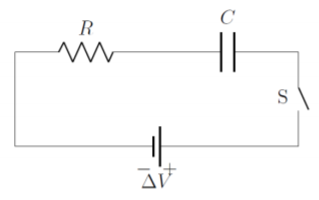
So far, we have modeled circuits where the current does not change with time. When a capacitor is included in a circuit, the current will change with time, as the capacitor charges or discharges. The circuit shown in Figure 20.5.1 shows an ideal battery1 (ΔV), in series with a resistor (R), a capacitor (C, two vertical bars) and a switch (S) that is open.
When the switch is open, current cannot flow through the circuit. If we assume that the capacitor has no charge on it, once we close the switch, current will start to flow and charges will accumulate on the capacitor. Electrons will leave the negative terminal of the battery, flow through the resistor and accumulate on the left side of the capacitor, which acquires a negative charge. This pushes electrons off of the right hand side of the capacitor, which then becomes positively charged. The electrons from the positive side of the capacitor then flow into the positive side of the battery, completing the circuit.
Eventually, the charges on the capacitor will build up to a point were they prevent any further flow of current. Once the left side of the capacitor is at the same potential as the left side of the battery, current will cease to flow. That is, eventually, the potential difference across the capacitor will be equal to that across the battery, and we can think of this as a circuit used to charge a capacitor. The current is high when the switch is first opened, but eventually goes down to zero as the capacitor charges. The current is thus time-dependent.
We can model this simple circuit (with the switch closed) using Kirchhoff’s loop rule. The sum of the voltages across each component must sum to zero:
ΔV−IR−QC=0
where we used the fact that the charge, Q, on a capacitor is related to the potential difference, ΔVC, across the capacitor by Q=CΔVC. The current, I, is the rate at which charges flow through the circuit, and is thus equal to rate at which charges accumulate on the capacitor:
I=dQdt
Substituting this into the loop equation, we obtain a separable differential equation for the charge on the capacitor as a function of time, Q(t):
ΔV−IR−QC=0ΔV−dQdtR−QC=0ΔV−QC=dQdtRCΔV−Q=RCdQdt∴dtRC=dQCΔV−Q
This is similar to differential equations that we have solved previously (in fact, it is the same equation as in Example 6.2.3 where we looked at the effect of velocity-dependent drag). The solution to the equation, assuming that the switch is closed at t=0, is given by an exponential:
Q(t)=CΔV(1−e−tRC)
Thus, the charge on the capacitor starts at zero when the switch is closed, and grows asymptotically until it reaches a value of Q=CΔV, which corresponds to the capacitor having the same potential difference across it as the battery. The value τ=RC is called the “time constant” of the RC circuit, and corresponds to the time at which the capacitor will reach about (1−e−1)=63% of its maximal charge. The current as a function of time is given by:
I(t)=dQdt=ΔVRe−tRC
and we can see that at time t=0 the current is the same as if there were no capacitor present, and the current then decreases exponentially until it reaches zero.
Footnotes
1. The model still holds for a real battery, since the internal resistance of the battery can just be included into the resistance of the resistor, R.