15.9: Alternating-Current Circuits (Exercise)


- Last updated
- Mar 3, 2025
- Save as PDF

( \newcommand{\kernel}{\mathrm{null}\,}\)
Conceptual Questions
15.2 AC Sources
1. What is the relationship between frequency and angular frequency?
15.3 Simple AC Circuits
2. Explain why at high frequencies a capacitor acts as an ac short, whereas an inductor acts as an open circuit.
15.4 RLC Series Circuits with AC
3. In an RLC series circuit, can the voltage measured across the capacitor be greater than the voltage of the source? Answer the same question for the voltage across the inductor.
15.5 Power in an AC Circuit
4. For what value of the phase angle ϕ between the voltage output of an ac source and the current is the average power output of the source a maximum?
5. Discuss the differences between average power and instantaneous power.
6. The average ac current delivered to a circuit is zero. Despite this, power is dissipated in the circuit. Explain.
7. Can the instantaneous power output of an ac source ever be negative? Can the average power output be negative?
8. The power rating of a resistor used in ac circuits refers to the maximum average power dissipated in the resistor. How does this compare with the maximum instantaneous power dissipated in the resistor?
15.7 Transformers
9. Why do transmission lines operate at very high voltages while household circuits operate at fairly small voltages?
10. How can you distinguish the primary winding from the secondary winding in a step-up transformer?
11. Battery packs in some electronic devices are charged using an adapter connected to a wall socket. Speculate as to the purpose of the adapter.
12. Will a transformer work if the input is a dc voltage?
13. Why are the primary and secondary coils of a transformer wrapped around the same closed loop of iron?
Problems
15.2 AC Sources
14. Write an expression for the output voltage of an ac source that has an amplitude of 12 V and a frequency of 200 Hz.
15.3 Simple AC Circuits
15. Calculate the reactance of a 5.0-μF capacitor at
(a) 60 Hz,
(b) 600 Hz, and
(c) 6000 Hz.
16. What is the capacitance of a capacitor whose reactance is 10Ω at 60 Hz?
17. Calculate the reactance of a 5.0-mH inductor at
(a) 60 Hz,
(b) 600 Hz, and
(c) 6000 Hz.
18. What is the self-inductance of a coil whose reactance is 10Ω at 60 Hz?
19. At what frequency is the reactance of a 20-μF capacitor equal to that of a 10-mH inductor?
20. At 1000 Hz, the reactance of a 5.0-mH inductor is equal to the reactance of a particular capacitor. What is the capacitance of the capacitor?
21. A 50-Ω resistor is connected across the emf v(t)=(160V)sin(120πt). Write an expression for the current through the resistor.
22. A 25-μF capacitor is connected to an emf given by v(t)=(160V)sin(120πt).
(a) What is the reactance of the capacitor?
(b) Write an expression for the current output of the source.
23. A 100-mH inductor is connected across the emf of the preceding problem.
(a) What is the reactance of the inductor?
(b) Write an expression for the current through the inductor.
15.4 RLC Series Circuits with AC
24. What is the impedance of a series combination of a 50-Ω resistor, a 5.0-μF5.0-μF capacitor, and a 10-μF10-μF capacitor at a frequency of 2.0 kHz?
25. A resistor and capacitor are connected in series across an ac generator. The emf of the generator is given by v(t)=V0cosωt, where V0=120V,ω=120πrad/s,R=400Ω, and C=4.0μF.
(a) What is the impedance of the circuit?
(b) What is the amplitude of the current through the resistor?
(c) Write an expression for the current through the resistor.
(d) Write expressions representing the voltages across the resistor and across the capacitor.
26. A resistor and inductor are connected in series across an ac generator. The emf of the generator is given by v(t)=V0cosωt, where V0=120V and ω=120πrad/s; also, R=400Ω and L=1.5H.
(a) What is the impedance of the circuit?
(b) What is the amplitude of the current through the resistor?
(c) Write an expression for the current through the resistor.
(d) Write expressions representing the voltages across the resistor and across the inductor.
27. In an RLC series circuit, the voltage amplitude and frequency of the source are 100 V and 500 Hz, respectively, an R=500Ω,L=0.20H, and C=2.0μF.
(a) What is the impedance of the circuit?
(b) What is the amplitude of the current from the source?
(c) If the emf of the source is given by v(t)=(100V)sin1000πt, how does the current vary with time?
(d) Repeat the calculations with i changed to 0.20μF.
28. An RLC series circuit with R=600Ω,L=30mH, and C=0.050μF is driven by an ac source whose frequency and voltage amplitude are 500 Hz and 50 V, respectively.
(a) What is the impedance of the circuit?
(b) What is the amplitude of the current in the circuit?
(c) What is the phase angle between the emf of the source and the current?
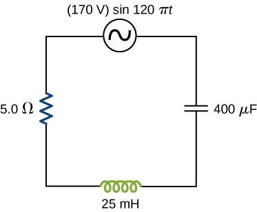
29. For the circuit shown below, what are
(a) the total impedance and
(b) the phase angle between the current and the emf?
(c) Write an expression for i(t).
15.5 Power in an AC Circuit
30. The emf of an ac source is given by v(t)=V0sinωt, where V0=100V and ω=200πrad/s.. Calculate the average power output of the source if it is connected across
(a) a 20-μF capacitor,
(b) a 20-mH inductor, and
(c) a 50-Ω resistor.
31. Calculate the rms currents for an ac source is given by v(t)=V0sinωt, where V0=100V and ω=200πrad/s when connected across
(a) a 20-μF capacitor,
(b) a 20-mH inductor, and
(c) a 50-Ω resistor.
32. A 40-mH inductor is connected to a 60-Hz AC source whose voltage amplitude is 50 V. If an AC voltmeter is placed across the inductor, what does it read?
33. For an RLC series circuit, the voltage amplitude and frequency of the source are 100 V and 500 Hz, respectively; R=500Ω; and L=0.20H. Find the average power dissipated in the resistor for the following values for the capacitance:
(a) C=2.0μF and
(b) C=0.20μF.
34. An ac source of voltage amplitude 10 V delivers electric energy at a rate of 0.80 W when its current output is 2.5 A. What is the phase angle ϕ between the emf and the current?
35. An RLC series circuit has an impedance of 60Ω and a power factor of 0.50, with the voltage lagging the current. (a) Should a capacitor or an inductor be placed in series with the elements to raise the power factor of the circuit? (b) What is the value of the reactance across the inductor that will raise the power factor to unity?
15.6 Resonance in an AC Circuit
36. (a) Calculate the resonant angular frequency of an RLC series circuit for which R=20Ω,L=75mH, and C=4.0μF. (b) If R is changed to 300Ω, what happens to the resonant angular frequency?
37. The resonant frequency of an RLC series circuit is 2.0×10³Hz. If the self-inductance in the circuit is 5.0 mH, what is the capacitance in the circuit?
38. (a) What is the resonant frequency of an RLC series circuit with R=20Ω, L=2.0mH, and C=4.0μF?
(b) What is the impedance of the circuit at resonance?
39. For an RLC series circuit, R=100Ω, L=150mH, and C=0.25μF.
(a) If an ac source of variable frequency is connected to the circuit, at what frequency is maximum power dissipated in the resistor?
(b) What is the quality factor of the circuit?
40. An ac source of voltage amplitude 100 V and variable frequency f drives an RLC series circuit with R=10Ω, L=2.0mH, and C=25μF.
(a) Plot the current through the resistor as a function of the frequency f.
(b) Use the plot to determine the resonant frequency of the circuit.
41. (a) What is the resonant frequency of a resistor, capacitor, and inductor connected in series if R=100Ω, L=2.0H, and C=5.0μF?
(b) If this combination is connected to a 100-V source operating at the constant frequency, what is the power output of the source?
(c) What is the Q of the circuit?
(d) What is the bandwidth of the circuit?
42. Suppose a coil has a self-inductance of 20.0 H and a resistance of 200Ω. What
(a) capacitance and
(b) resistance must be connected in series with the coil to produce a circuit that has a resonant frequency of 100 Hz and a Q of 10?
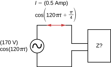
43. An ac generator is connected to a device whose internal circuits are not known. We only know current and voltage outside the device, as shown below. Based on the information given, what can you infer about the electrical nature of the device and its power usage?
15.7 Transformers
44. A step-up transformer is designed so that the output of its secondary winding is 2000 V (rms) when the primary winding is connected to a 110-V (rms) line voltage.
(a) If there are 100 turns in the primary winding, how many turns are there in the secondary winding?
(b) If a resistor connected across the secondary winding draws an rms current of 0.75 A, what is the current in the primary winding?
45. A step-up transformer connected to a 110-V line is used to supply a hydrogen-gas discharge tube with 5.0 kV (rms). The tube dissipates 75 W of power.
(a) What is the ratio of the number of turns in the secondary winding to the number of turns in the primary winding?
(b) What are the rms currents in the primary and secondary windings?
(c) What is the effective resistance seen by the 110-V source?
46. An ac source of emf delivers 5.0 mW of power at an rms current of 2.0 mA when it is connected to the primary coil of a transformer. The rms voltage across the secondary coil is 20 V.
(a) What are the voltage across the primary coil and the current through the secondary coil?
(b) What is the ratio of secondary to primary turns for the transformer?
47. A transformer is used to step down 110 V from a wall socket to 9.0 V for a radio.
(a) If the primary winding has 500 turns, how many turns does the secondary winding have?
(b) If the radio operates at a current of 500 mA, what is the current through the primary winding?
48. A transformer is used to supply a 12-V model train with power from a 110-V wall plug. The train operates at 50 W of power.
(a) What is the rms current in the secondary coil of the transformer?
(b) What is the rms current in the primary coil?
(c) What is the ratio of the number of primary to secondary turns?
(d) What is the resistance of the train?
(e) What is the resistance seen by the 110-V source?
Additional Problems
49. The emf of an dc source is given by v(t)=V0sinωt, where V0=100V and ω=200πrad/s. Find an expression that represents the output current of the source if it is connected across
(a) a 20-μF capacitor,
(b) a 20-mH inductor, and
(c) a 50-Ω resistor.
50. A 700-pF capacitor is connected across an ac source with a voltage amplitude of 160 V and a frequency of 20 kHz.
(a) Determine the capacitive reactance of the capacitor and the amplitude of the output current of the source.
(b) If the frequency is changed to 60 Hz while keeping the voltage amplitude at 160 V, what are the capacitive reactance and the current amplitude?
51. A 20-mH inductor is connected across an AC source with a variable frequency and a constant-voltage amplitude of 9.0 V.
(a) Determine the reactance of the circuit and the maximum current through the inductor when the frequency is set at 20 kHz.
(b) Do the same calculations for a frequency of 60 Hz.
52. A 30-μF capacitor is connected across a 60-Hz ac source whose voltage amplitude is 50 V.
(a) What is the maximum charge on the capacitor?
(b) What is the maximum current into the capacitor?
(c) What is the phase relationship between the capacitor charge and the current in the circuit?
53. A 7.0-mH inductor is connected across a 60-Hz ac source whose voltage amplitude is 50 V.
(a) What is the maximum current through the inductor?
(b) What is the phase relationship between the current through and the potential difference across the inductor?
54. What is the impedance of an RLC series circuit at the resonant frequency?
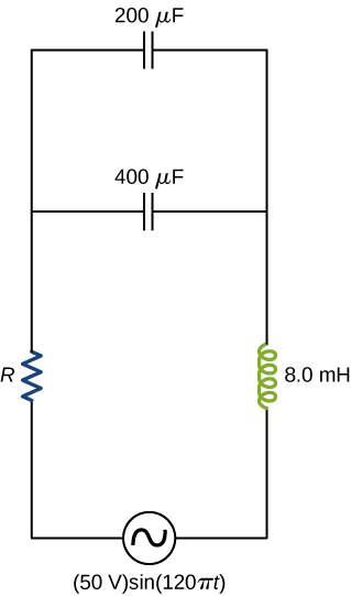
55. What is the resistance R in the circuit shown below if the amplitude of the ac through the inductor is 4.24 A?
56. An ac source of voltage amplitude 100 V and frequency 1.0 kHz drives an RLC series circuit with R=20Ω, L=4.0mH, and C=50μF.
(a) Determine the rms current through the circuit.
(b) What are the rms voltages across the three elements?
(c) What is the phase angle between the emf and the current?
(d) What is the power output of the source?
(e) What is the power dissipated in the resistor?
57. In an RLC series circuit, R=200Ω,L=1.0H,C=50μF,V0=120V, and f=50Hz. What is the power output of the source?
58. A power plant generator produces 100 A at 15 kV (rms). A transformer is used to step up the transmission line voltage to 150 kV (rms).
(a) What is rms current in the transmission line?
(b) If the resistance per unit length of the line is 8.6×10⁻⁸Ω/m, what is the power loss per meter in the line?
(c) What would the power loss per meter be if the line voltage were 15 kV (rms)?
59. Consider a power plant located 25 km outside a town delivering 50 MW of power to the town. The transmission lines are made of aluminum cables with a 7cm2 cross-sectional area. Find the loss of power in the transmission lines if it is transmitted at
(a) 200 kV (rms) and
(b) 120 V (rms).
60. Neon signs require 12-kV for their operation. A transformer is to be used to change the voltage from 220-V (rms) ac to 12-kV (rms) ac.
(a) What must the ratio be of turns in the secondary winding to the turns in the primary winding?
(b) What is the maximum rms current the neon lamps can draw if the fuse in the primary winding goes off at 0.5 A?
(c) How much power is used by the neon sign when it is drawing the maximum current allowed by the fuse in the primary winding?
Challenge Problems
61. The 335-kV ac electricity from a power transmission line is fed into the primary winding of a transformer. The ratio of the number of turns in the secondary winding to the number in the primary winding is Ns/Np=1000.
(a) What voltage is induced in the secondary winding?
(b) What is unreasonable about this result?
(c) Which assumption or premise is responsible?
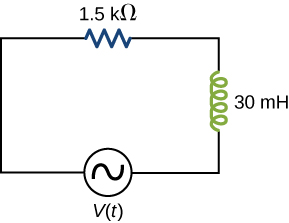
62. A 1.5-kΩ resistor and 30-mH inductor are connected in series, as shown below, across a 120-V (rms) ac power source oscillating at 60-Hz frequency.
(a) Find the current in the circuit.
(b) Find the voltage drops across the resistor and inductor.
(c) Find the impedance of the circuit.
(d) Find the power dissipated in the resistor.
(e) Find the power dissipated in the inductor.
(f) Find the power produced by the source.
63. A 20-Ω resistor, 50-μF capacitor, and 30-mH inductor are connected in series with an ac source of amplitude 10 V and frequency 125 Hz.
(a) What is the impedance of the circuit?
(b) What is the amplitude of the current in the circuit?
(c) What is the phase constant of the current? Is it leading or lagging the source voltage?
(d) Write voltage drops across the resistor, capacitor, and inductor and the source voltage as a function of time.
(e) What is the power factor of the circuit? (f) How much energy is used by the resistor in 2.5 s?
64. A 200-Ω resistor, 150-μF capacitor, and 2.5-H inductor are connected in series with an ac source of amplitude 10 V and variable angular frequency ω.
(a) What is the value of the resonance frequency ωR?
(b) What is the amplitude of the current if ω=ωR?
(c) What is the phase constant of the current when ω=ωR? Is it leading or lagging the source voltage, or is it in phase?
(d) Write an equation for the voltage drop across the resistor as a function of time when ω=ωR.
(e) What is the power factor of the circuit when ω=ωR?
(f) How much energy is used up by the resistor in 2.5 s when ω=ωR?
65. Find the reactances of the following capacitors and inductors in ac circuits with the given frequencies in each case:
(a) 2-mH inductor with a frequency 60-Hz of the ac circuit;
(b) 2-mH inductor with a frequency 600-Hz of the ac circuit;
(c) 20-mH inductor with a frequency 6-Hz of the ac circuit;
(d) 20-mH inductor with a frequency 60-Hz of the ac circuit;
(e) 2-mF capacitor with a frequency 60-Hz of the ac circuit; and
(f) 2-mF capacitor with a frequency 600-Hz of the AC circuit.
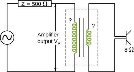
66. An output impedance of an audio amplifier has an impedance of 500Ω and has a mismatch with a low-impedance 8-Ω loudspeaker. You are asked to insert an appropriate transformer to match the impedances. What turns ratio will you use, and why? Use the simplified circuit shown below.
67. Show that the SI unit for capacitive reactance is the ohm. Show that the SI unit for inductive reactance is also the ohm.
68. A coil with a self-inductance of 16 mH and a resistance of 6.0Ω is connected to an ac source whose frequency can be varied. At what frequency will the voltage across the coil lead the current through the coil by 45°?
69. An RLC series circuit consists of a 50-Ω resistor, a 200-μF capacitor, and a 120-mH inductor whose coil has a resistance of 20Ω. The source for the circuit has an rms emf of 240 V at a frequency of 60 Hz. Calculate the rms voltages across the
(a) resistor,
(b) capacitor, and
(c) inductor.
70. An RLC series circuit consists of a 10-Ω resistor, an 8.0-μF capacitor, and a 50-mH inductor. A 110-V (rms) source of variable frequency is connected across the combination. What is the power output of the source when its frequency is set to one-half the resonant frequency of the circuit?
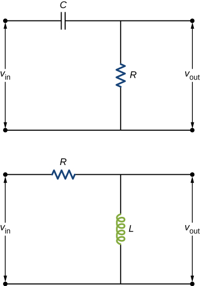
71. Shown below are two circuits that act as crude high-pass filters. The input voltage to the circuits is vin, and the output voltage is vout.vout.
(a) Show that for the capacitor circuit, voutvin=1√1+1/ω2R2C2, and for the inductor circuit, voutvin=ωL√R2+ω2L2.
(b) Show that for high frequencies, vout≈vin, but for low frequencies, vout≈0.
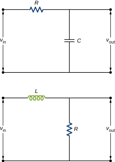
72. The two circuits shown below act as crude low-pass filters. The input voltage to the circuits is vin, and the output voltage is vout.
(a) Show that for the capacitor circuit, voutvin=1√1+ω2R2C2, and for the inductor circuit, voutvin=R√R2+ω2L2.
(b) Show that for low frequencies, vout≈vin, but for high frequencies, vout≈0.