B13: RC Circuit
- Page ID
- 5944

\( \newcommand{\vecs}[1]{\overset { \scriptstyle \rightharpoonup} {\mathbf{#1}} } \)
\( \newcommand{\vecd}[1]{\overset{-\!-\!\rightharpoonup}{\vphantom{a}\smash {#1}}} \)
\( \newcommand{\dsum}{\displaystyle\sum\limits} \)
\( \newcommand{\dint}{\displaystyle\int\limits} \)
\( \newcommand{\dlim}{\displaystyle\lim\limits} \)
\( \newcommand{\id}{\mathrm{id}}\) \( \newcommand{\Span}{\mathrm{span}}\)
( \newcommand{\kernel}{\mathrm{null}\,}\) \( \newcommand{\range}{\mathrm{range}\,}\)
\( \newcommand{\RealPart}{\mathrm{Re}}\) \( \newcommand{\ImaginaryPart}{\mathrm{Im}}\)
\( \newcommand{\Argument}{\mathrm{Arg}}\) \( \newcommand{\norm}[1]{\| #1 \|}\)
\( \newcommand{\inner}[2]{\langle #1, #2 \rangle}\)
\( \newcommand{\Span}{\mathrm{span}}\)
\( \newcommand{\id}{\mathrm{id}}\)
\( \newcommand{\Span}{\mathrm{span}}\)
\( \newcommand{\kernel}{\mathrm{null}\,}\)
\( \newcommand{\range}{\mathrm{range}\,}\)
\( \newcommand{\RealPart}{\mathrm{Re}}\)
\( \newcommand{\ImaginaryPart}{\mathrm{Im}}\)
\( \newcommand{\Argument}{\mathrm{Arg}}\)
\( \newcommand{\norm}[1]{\| #1 \|}\)
\( \newcommand{\inner}[2]{\langle #1, #2 \rangle}\)
\( \newcommand{\Span}{\mathrm{span}}\) \( \newcommand{\AA}{\unicode[.8,0]{x212B}}\)
\( \newcommand{\vectorA}[1]{\vec{#1}} % arrow\)
\( \newcommand{\vectorAt}[1]{\vec{\text{#1}}} % arrow\)
\( \newcommand{\vectorB}[1]{\overset { \scriptstyle \rightharpoonup} {\mathbf{#1}} } \)
\( \newcommand{\vectorC}[1]{\textbf{#1}} \)
\( \newcommand{\vectorD}[1]{\overrightarrow{#1}} \)
\( \newcommand{\vectorDt}[1]{\overrightarrow{\text{#1}}} \)
\( \newcommand{\vectE}[1]{\overset{-\!-\!\rightharpoonup}{\vphantom{a}\smash{\mathbf {#1}}}} \)
\( \newcommand{\vecs}[1]{\overset { \scriptstyle \rightharpoonup} {\mathbf{#1}} } \)
\(\newcommand{\longvect}{\overrightarrow}\)
\( \newcommand{\vecd}[1]{\overset{-\!-\!\rightharpoonup}{\vphantom{a}\smash {#1}}} \)
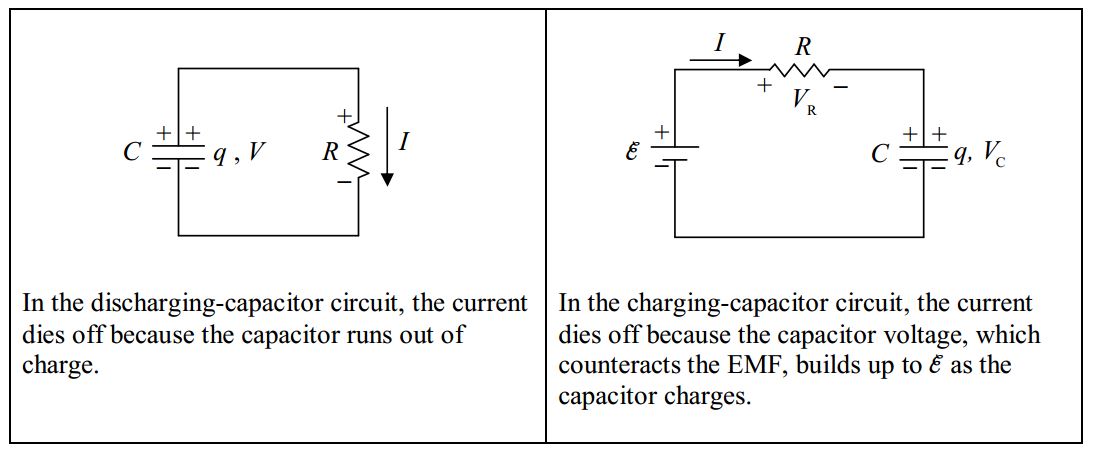
\(\newcommand{\avec}{\mathbf a}\) \(\newcommand{\bvec}{\mathbf b}\) \(\newcommand{\cvec}{\mathbf c}\) \(\newcommand{\dvec}{\mathbf d}\) \(\newcommand{\dtil}{\widetilde{\mathbf d}}\) \(\newcommand{\evec}{\mathbf e}\) \(\newcommand{\fvec}{\mathbf f}\) \(\newcommand{\nvec}{\mathbf n}\) \(\newcommand{\pvec}{\mathbf p}\) \(\newcommand{\qvec}{\mathbf q}\) \(\newcommand{\svec}{\mathbf s}\) \(\newcommand{\tvec}{\mathbf t}\) \(\newcommand{\uvec}{\mathbf u}\) \(\newcommand{\vvec}{\mathbf v}\) \(\newcommand{\wvec}{\mathbf w}\) \(\newcommand{\xvec}{\mathbf x}\) \(\newcommand{\yvec}{\mathbf y}\) \(\newcommand{\zvec}{\mathbf z}\) \(\newcommand{\rvec}{\mathbf r}\) \(\newcommand{\mvec}{\mathbf m}\) \(\newcommand{\zerovec}{\mathbf 0}\) \(\newcommand{\onevec}{\mathbf 1}\) \(\newcommand{\real}{\mathbb R}\) \(\newcommand{\twovec}[2]{\left[\begin{array}{r}#1 \\ #2 \end{array}\right]}\) \(\newcommand{\ctwovec}[2]{\left[\begin{array}{c}#1 \\ #2 \end{array}\right]}\) \(\newcommand{\threevec}[3]{\left[\begin{array}{r}#1 \\ #2 \\ #3 \end{array}\right]}\) \(\newcommand{\cthreevec}[3]{\left[\begin{array}{c}#1 \\ #2 \\ #3 \end{array}\right]}\) \(\newcommand{\fourvec}[4]{\left[\begin{array}{r}#1 \\ #2 \\ #3 \\ #4 \end{array}\right]}\) \(\newcommand{\cfourvec}[4]{\left[\begin{array}{c}#1 \\ #2 \\ #3 \\ #4 \end{array}\right]}\) \(\newcommand{\fivevec}[5]{\left[\begin{array}{r}#1 \\ #2 \\ #3 \\ #4 \\ #5 \\ \end{array}\right]}\) \(\newcommand{\cfivevec}[5]{\left[\begin{array}{c}#1 \\ #2 \\ #3 \\ #4 \\ #5 \\ \end{array}\right]}\) \(\newcommand{\mattwo}[4]{\left[\begin{array}{rr}#1 \amp #2 \\ #3 \amp #4 \\ \end{array}\right]}\) \(\newcommand{\laspan}[1]{\text{Span}\{#1\}}\) \(\newcommand{\bcal}{\cal B}\) \(\newcommand{\ccal}{\cal C}\) \(\newcommand{\scal}{\cal S}\) \(\newcommand{\wcal}{\cal W}\) \(\newcommand{\ecal}{\cal E}\) \(\newcommand{\coords}[2]{\left\{#1\right\}_{#2}}\) \(\newcommand{\gray}[1]{\color{gray}{#1}}\) \(\newcommand{\lgray}[1]{\color{lightgray}{#1}}\) \(\newcommand{\rank}{\operatorname{rank}}\) \(\newcommand{\row}{\text{Row}}\) \(\newcommand{\col}{\text{Col}}\) \(\renewcommand{\row}{\text{Row}}\) \(\newcommand{\nul}{\text{Nul}}\) \(\newcommand{\var}{\text{Var}}\) \(\newcommand{\corr}{\text{corr}}\) \(\newcommand{\len}[1]{\left|#1\right|}\) \(\newcommand{\bbar}{\overline{\bvec}}\) \(\newcommand{\bhat}{\widehat{\bvec}}\) \(\newcommand{\bperp}{\bvec^\perp}\) \(\newcommand{\xhat}{\widehat{\xvec}}\) \(\newcommand{\vhat}{\widehat{\vvec}}\) \(\newcommand{\uhat}{\widehat{\uvec}}\) \(\newcommand{\what}{\widehat{\wvec}}\) \(\newcommand{\Sighat}{\widehat{\Sigma}}\) \(\newcommand{\lt}{<}\) \(\newcommand{\gt}{>}\) \(\newcommand{\amp}{&}\) \(\definecolor{fillinmathshade}{gray}{0.9}\)Suppose you connect a capacitor across a battery, and wait until the capacitor is charged to the extent that the voltage across the capacitor is equal to the EMF \*V_0\) of the battery. Further suppose that you remove the capacitor from the battery. You now have a capacitor with voltage \(V_0\) and charge \(q_o\), where \(q_o = C V_0\).
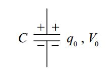
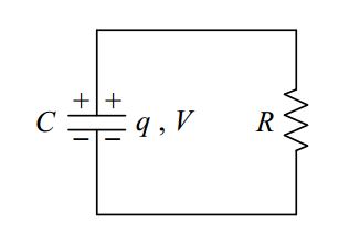
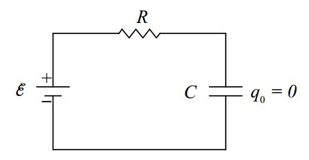
The capacitor is said to be charged. Now suppose that you connect the capacitor in series with an open switch and a resistor as depicted below.
The capacitor remains charged as long as the switch remains open. Now suppose that, at a clock reading we shall call time zero, you close the switch.
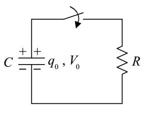
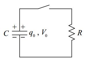
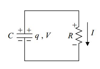
From time \(0\) on, the circuit is:
The potential across the resistor is now the same as the potential across the capacitor. This results in current through the resistor:
Positive charge flows from the upper plate of the capacitor, down through the resistor to the lower plate of the capacitor. The capacitor is said to be discharging. As the charge on the capacitor decreases; according to \(q = CV\), which can be written \(V = q/C\), the voltage across the capacitor decreases. But, as is clear from the diagram, the voltage across the capacitor is the voltage across the resistor. What we are saying is that the voltage across the resistor decreases. According to \(V = IR\), which can be written as \(I = V/R\), this means that the current through the resistor decreases. So, the capacitor continues to discharge at an ever decreasing rate. Eventually, the charge on the capacitor decreases to a negligible value, essentially zero, and the current dies down to a negligible value, essentially zero. Of interest is how the various quantities, the voltage across both circuit elements, the charge on the capacitor, and the current through the resistor depend on the time \(t\). Let’s apply the loop rule to the circuit while the capacitor is discharging:
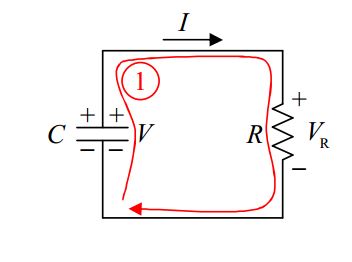
\[KVL\space 1+V-V_R=0 \nonumber \]
Using \(q = CV\) expressed as \(V=\dfrac{q}{C}\) and \(V_R=IR\), we obtain
\[\dfrac{q}{C}-IR=0 \nonumber \]
\(I\) is the charge flow rate through the resistor, which is equivalent to the rate at which charge is being depleted from the capacitor (since the charge flowing through the resistor comes from the capacitor). Thus \(I\) is the negative of the rate of change of the charge on the capacitor:
\[I=-\dfrac{dq}{dt} \nonumber \]
Substituting this (\(I=-\dfrac{dq}{dt}\) ) into our loop rule equation (\(\dfrac{q}{C}-IR=0\)) yields:
\[\dfrac{q}{C}+\dfrac{dq}{dt} R=0 \nonumber \]
\[\dfrac{dq}{dt}=-\dfrac{1}{RC} q \nonumber \]
Thus \(q(t)\) is a function whose derivative with respect to time is itself, times the constant \(-\dfrac{1}{RC}\). The function is essentially its own derivative. This brings the exponential function \(e^{t}\) to mind. The way to get that constant (\(-\dfrac{1}{RC}\)) to appear when we take the derivative of \(q(t)\) with respect to t is to include it in the exponent. Try \(q(t)=q_o\space e^{-\dfrac{1}{RC} t}\). Now, when you apply the chain rule for the function of a function you get \(\dfrac{dq}{dt}=-\dfrac{1}{RC}q\) which is just what we wanted. Let’s check the units. \(R\) was defined as \(\dfrac{V}{I}\) meaning the ohm is a volt per ampere. And \(C\) was defined as \(\dfrac{q}{V}\) meaning that the farad is a coulomb per volt. So the units of the product \(RC\) are:
\[[RC]=\dfrac{V}{A} \dfrac{\mbox{coulombs}}{V}=\dfrac{\mbox{coulombs}}{A}=\dfrac{\mbox{coulombs}}{\mbox{coulombs/s}}=s \nonumber \]
So the exponent in \(e^{-\dfrac{1}{RC}t}\) is unitless. That works. We can’t raise \(e\) to something that has units. Now, about that \(q_o\) out front in \(q=q_o e^{-\dfrac{1}{RC}t}\). The exponential evaluates to a unitless quantity. So we need to put the qo there to get units of charge. If you plug the value \(0\) in for the time in \(q=q_o e^{-\dfrac{1}{RC}t}\) you get \(q=q_o\). Thus, \(q_o\) is the initial value of the charge on the capacitor. One final point: The product \(RC\) is called the “\(RC\) time constant.” The symbol \(\tau\) is often used to represent that time constant. In other words,
\[\tau=RC \label{13-1} \]
where \(\tau\) is also referred to as the \(RC\) time constant. In terms of \(\tau\), our expression for \(q\) becomes:
\[q=q_o e^{-\dfrac{t}{\tau}} \nonumber \]
which we copy here for your convenience:
\[q=q_o e^{-\dfrac{t}{\tau}} \nonumber \]
Note that when \(t = \tau\), we have
\[q=q_o e^{-1} \nonumber \]
\[q=\dfrac{1}{e} q_o \nonumber \]
\(\dfrac{1}{e}\) is \(.368\) so \(\tau\) is the time it takes for \(q\) to become \(36.8%\) of its original value.
With our expression for \(q\) in hand, it is easy to get the expression for the voltage across the capacitor (which is the same as the voltage across the resistor, \(V_C = V_R\) ) which we have been calling \(V\). Substituting our expression \(q=q_o e^{-\dfrac{1}{RC}t}\) into the defining equation for capacitance \(q = CV\) solved for \(V\),
\[V=\dfrac{q}{C} \nonumber \]
yields:
\[V=\dfrac{q_o}{C} e^{-\dfrac{1}{RC}t} \nonumber \]
But if \(q_o\) is the charge on the capacitor at time \(0\), then \(q_o = CV_0\) where \(V_0\) is the voltage across the capacitor at time \(0\) or:
\[\dfrac{q_o}{C}=V_o. \nonumber \]
Substituting \(V_o\) for \(\dfrac{q_o}{C}\) in \(V=\dfrac{q_o}{C} e^{-\dfrac{1}{RC}t}\) above yields:
\[V=V_o e^{-\dfrac{t}{RC}} \label{13-2} \]
for both the voltage across the capacitor and the voltage across the resistor. From, the defining equation for resistance:
\[V=IR, \nonumber \]
we can write:
\[I=\dfrac{V}{R} \nonumber \]
Substituting our expression \(V_o e^{-\dfrac{t}{RC}}\) in for \(V\) turns this equation \(\Big ( I=\dfrac{V}{R}\Big )\) into:
\[I=\dfrac{V_o e^{-\dfrac{t}{RC}}}{R} \nonumber \]
But, \(\dfrac{V_o}{R}\) is just \(I_0\) (from \(V_0 = I_0 R\) solved for \(I_0\) ), the current at the time \(0\), so:
\[I=I_0 e^{-\dfrac{t}{RC}}\label{13-3} \]
Summarizing, we note that all three of the quantities, \(V\), \(I\), and \(q\) decrease exponentially with time.
Charging Circuit
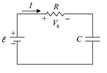
Consider the following circuit, containing an initially-uncharged capacitor, and
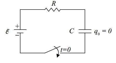
annotated to indicate that the switch is closed at time \(0\) at which point the circuit becomes:
Let’s think about what will happen as time elapses. With no charge on the capacitor, the voltage across it is zero, meaning the potential of the right terminal of the resistor is the same as the potential of the lower-potential terminal of the seat of EMF. Since the left end of the resistor is connected to the higher-potential terminal of the seat of EMF, this means that at time \(0\), the voltage across the resistor is equivalent to the EMF \(\varepsilon\) of the seat of EMF. Thus, there will be a rightward current through the resistor.
The positive charge flowing through the resistor has to come from someplace. Where does it come from? Answer: The bottom plate of the capacitor. Also, charge can’t flow through an ideal capacitor. So where does it go? It piles up on the top plate of the capacitor.
The capacitor is becoming charged. As it does, the voltage across the capacitor increases, meaning the potential of the right terminal of the resistor (relative to the potential of the lowerpotential terminal of the seat of EMF) increases. The potential of the left terminal of the resistor remains constant, as dictated by the seat of EMF. This means that the voltage across the resistor continually decreases. This, in turn; from \(V_R = IR\), written as \(I = V_R/R\), means that the current continually decreases. This occurs until there is so much charge on the capacitor that \(V_c = \varepsilon\), meaning that \(V_R = 0\) so \(I = 0\).
Recapping our conceptual discussion:
At time 0, we close the switch:
- The charge on the capacitor starts off at 0 and builds up to \(q = C\varepsilon\) where \(\varepsilon\) is the EMF voltage.
- The capacitor voltage starts off at \(0\) and builds up to the EMF voltage \(\varepsilon\).
- The current starts off at \(I_o=\dfrac{\varepsilon}{R}\) and decreases to \(0\).
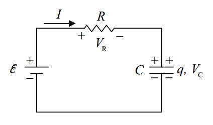
Okay, we have a qualitative understanding of what happens. Let’s see if we can obtain formulas for \(V_R\), \(I\), \(V_C\), and \(q\) as functions of time. Here’s the circuit:
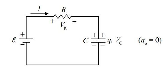
We apply the loop rule:
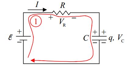
\[KVL 1+\varepsilon-V_R+V_C=0 \nonumber \]
and the definitions of resistance and capacitance:
\[V_R=IR \nonumber \]
\[q=CV_C \nonumber \]
\[V_C=\dfrac{q}{C} \nonumber \]
to obtain:
\[\varepsilon-IR-\dfrac{q}{C}=0 \nonumber \]
\[IR+\dfrac{q}{C}=\varepsilon \nonumber \]
Then we use the fact that the current is equal to the rate at which charge is building up on the capacitor, \(I=\dfrac{dq}{dt}\), to get:
\[\dfrac{dq}{dt}R+\dfrac{q}{C}=\varepsilon \nonumber \]
\[\dfrac{dq}{dt}+\dfrac{q}{RC}=\dfrac{\varepsilon}{R} \nonumber \]
This is interesting. This is the same equation that we had before, except that we have the constant \(\varepsilon/R\) on the right instead of \(0\).
For this equation, I’m simply going to provide and discuss the solution, rather than show you how to solve the differential equation. The charge function of time that solves this equation is:
\[q=C\varepsilon(1-e^{-\dfrac{t}{RC}}) \nonumber \]
Please substitute it into the differential equation (\(\dfrac{dq}{dt}+\dfrac{q}{RC}=\dfrac{\varepsilon}{R}\)) and verify that it leads to an identity.
Now let’s check to make sure that \(q=C\varepsilon (1-e^{-\dfrac{t}{RC}})\) is consistent with our conceptual understanding. At time zero \((t=0)\), our expression \(q(t)=C\varepsilon(1-e^{-\dfrac{t}{RC}})\) evaluates to:
\[q(0)=C\varepsilon(1-e^{-\dfrac{0}{RC}}) \nonumber \]
\[=C\varepsilon(1-e^{0}) \nonumber \]
\[=C\varepsilon(1-1) \nonumber \]
\[q(0)=0 \nonumber \]
Excellent. This is consistent with the fact that the capacitor starts out uncharged.
Now, what does our charge function \(q(t)=C\varepsilon(1-e^{-\dfrac{t}{RC}})\) say about what happens to the charge of the capacitor in the limit as \(t\) goes to infinity?
\[\lim_{t\to \infty}\space q(t)=\lim_{t\to \infty}\space C\varepsilon(1-e^{-\dfrac{t}{RC}}) \nonumber \]
\[=C\varepsilon\lim_{x\to \infty}\space(1-e^{-x}) \nonumber \]
\[=C\varepsilon\lim_{x\to \infty}\space(1-\dfrac{1}{e^x}) \nonumber \]
\[=C\varepsilon\lim_{y\to \infty}\space(1-\dfrac{1}{y}) \nonumber \]
\[=C\varepsilon\space(1-\lim_{y\to\infty} \dfrac{1}{y}) \nonumber \]
\[=C\varepsilon(1-0) \nonumber \]
\[\lim_{t\to \infty}\space q(t)=C\varepsilon \nonumber \]
Well, this makes sense. Our conceptual understanding was that the capacitor would keep charging until the voltage across the capacitor was equal to the voltage across the seat of EMF. From the definition of capacitance, when the capacitor voltage is \(\varepsilon\), its charge is indeed \(C\varepsilon\). The formula yields the expected result for \(\lim_{t\to\infty} q(t)\).
Once we have \(q(t)\) it is pretty easy to get the other circuit quantities. For instance, from the definition of capacitance:
\[q=C V_c, \nonumber \]
we have \(V_c=q/C\) which, with \(1=C\varepsilon(1-e^{-\dfrac{t}{RC}})\) evaluates to:
\[V_c=\varepsilon (1-e^{-\dfrac{t}{RC}}) \label{13-4} \]
Our original loop equation read:
\[\varepsilon-V_R-V_c=0 \nonumber \]
So:
\[V_R=\varepsilon-V_c \nonumber \]
which, with \(V_c=\varepsilon (1-e^{-\dfrac{t}{RC}})\) can be written as:
\[V_R=\varepsilon-\varepsilon (1-e^{-\dfrac{t}{RC}}) \nonumber \]
\[V_R=\varepsilon-\varepsilon+\varepsilon e^{-\dfrac{t}{RC}} \nonumber \]
\[V_R=\varepsilon e^{-\dfrac{t}{RC}} \nonumber \]
From our definition of resistance:
\[V_R=IR \nonumber \]
\[I=\dfrac{V_R}{R} \nonumber \]
with \(V_R=\varepsilon e^{-\dfrac{t}{RC}}\), this can be expressed as:
\[I=\dfrac{\varepsilon}{R} e^{-\dfrac{t}{RC}} \nonumber \]
At time \(0\), this evaluates to \(\varepsilon/R\) meaning that \(\varepsilon/R\) can be interpreted as the current at time \(0\) allowing us to write our function \(I(t)\) as
\[I=I_o e^{-\dfrac{t}{RC}} \nonumber \]
Our formula has the current starting out at its maximum value and decreasing exponentially with time, as anticipated based on our conceptual understanding of the circuit. Note that this is the same formula that we got for the current in the discharging-capacitor circuit. In both cases, the current dies off exponentially. The reasons differ, but the effect (\(I=I_o e^{-\dfrac{t}{RC}}\)) is the same: