
17.2: Magnetic Induction and Inductors


- Last updated
- Nov 6, 2024
- Save as PDF

( \newcommand{\kernel}{\mathrm{null}\,}\)
Induction is the tendency of a current in a conductor to maintain itself in the face of changes in the potential difference driving the current. Figure 17.4 shows a parallel plate inductor in which a current i passes through the two plates in opposite directions.2 The vector potential between plates of width w and spacing d is
A=(−μ0izw,0,0),
as long as w ≫ d (see Figure 17.2.4:).
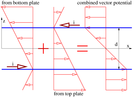
Let us try to understand how this vector potential is constructed from what we already know. The vector potential for a single current sheet in the x-y plane at z=0 moving in the x direction was computed in the previous chapter as Ax=−vσ|z|/(2ϵ0c2), with Ay=AZ=0. The quantity σ is the charge per unit area on the sheet and v is the velocity of the charge sheet in the x direction. We use the relationship 1∕(ϵ0c2) = μ 0 and also realize that if each plate has a width w, then the current in each plate is i=vσw, which means that we can rewrite Ax=−μ0i|z|/(2w) for a single plate.
To proceed further, we first need to understand that |z| in the above equation is only valid if the charge sheet is at z=0. If the sheet is located a distance a from the origin, then we must replace |z| by |z−a|. We also need to call on the definition of absolute value to realize that |z−a|=z−a if z>a, and |z−a|=−z+a if z<a . . Figure 17.2.5: shows how the profiles of AX from each of the charge sheets add together to form a combined profile for the two sheets together.
The resulting magnetic field between the plates can be computed from the vector potential:
B=(0,−μ0iw,0).
Above and below the plates the magnetic field is zero because the vector potential is constant.
Let us now ask what happens when the current through the inductor increases or decreases with time. Assuming initially that no scalar potential exists, the x component of the electric field in the device is
Ex=−∂Ax∂t=μ0zwdidt
while Ey=Ez=0. Substituting the z values for each plate, we see that
Ex−upper=+μ0d2wdidt( upper plate )Ex− lower =−μ0d2wdidt( lower plate ).
The EMF or work done by this electric field on a unit charge moving from the right end of the upper plate, around the wire loops at the left end, and back to the right end of the lower plate is
ΔV=Ex−upper(−l)+Ex−lower(+l)=−μ0dlwdidt
where l is the length of the plate, as illustrated in Figure 17.2.4:.
The minus sign means that the electric field acts so as to oppose a change in the current. This result is called Lenz’s law. Lenz’s law is not an independent law, but arises from the minus sign in the statement of Faraday’s law.
In order for the current i through the inductor to increase with time, an external potential difference Δϕ must be imposed between the input and output wires of the inductor, which just balances the effects of the internally generated electric field:
Δϕ=−ΔV=μ0dlwdidt( parallel plate inductor ).
If this potential difference is positive, i. e., if the input wire of the inductor is at a higher potential then the output wire, then the current through the inductor will increase with time. If it is lower, the current will decrease.
As with capacitors, inductors come in many shapes and forms. The above equation is valid only for a parallel plate inductor, but the relationship
Δϕ=Ldidt
is valid for any inductor, assuming that the inductance L is known. Comparison of the above two equations reveals that the inductance for the parallel plate inductor shown in Figure 17.2.4: is just
L=μ0dlw( parallel plate inductor ).