17.1: The Capacitor and Ampère’s Law
( \newcommand{\kernel}{\mathrm{null}\,}\)
We first discuss a device that is commonly used in electronics, called the capacitor. We then introduce a new mathematical idea called the circulation of a vector field around a loop. Finally, we use this idea to investigate Ampère’s law.
Capacitor
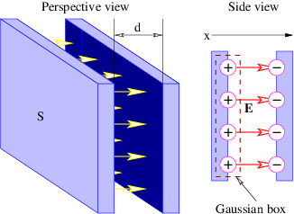
The capacitor is an electronic device for storing charge. The simplest type is the parallel plate capacitor, illustrated in Figure 17.1.1:. This consists of two conducting plates of area S separated by distance d, with the plate separation being much smaller than the plate dimensions. Positive charge q resides on one plate, while negative charge -q resides on the other.

The electric field between the plates is E=σ/ϵ0, where the charge per unit area on the inside of the left plate in Figure 17.1.1: is σ=q/S.. The density on the right plate is just -σ. All charge is assumed to reside on the inside surfaces and thus contributes to the electric field crossing the gap between the plates.
The above formula for the electric field comes from applying Gauss’s law to the sheet of charge on the positive plate. The factor of 1\2 present in the equation for an isolated sheet of charge is absent here because all of the electric flux exits the Gaussian surface on the right side — the left side of the Gaussian box is inside the conductor where the electric field is zero, at least in a static situation.
There is no vector potential in this case, so the electric field is related solely to the scalar potential ϕ. Integrating Ex=−∂ϕ/∂x across the gap between the conducting plates, we find that the potential difference between the plates is Δϕ=Exd=qd(ϵ0S) since Ex is known to be constant in this case. This equation indicates that the potential difference Δϕ is proportional to the charge q on the left plate of the capacitor in Figure 17.1.1:. The constant of proportionality is d/(ϵ0S), and the inverse of this constant is called the capacitance :
C=ϵ0Sd (parallel plate capacitor).
The relationship between potential difference, charge, and capacitance is thus
Δϕ=q/C or C=q/Δϕ
The equation for the capacitance of the illustrated parallel plates contains just a fundamental constant (ϵ0) and geometrical factors (area of plates, spacing between them), and represents the amount of charge the parallel plate capacitor can store per unit potential difference between the plates. A word about signs: The higher potential is always on the plate of the capacitor that has the positive charge.
Note that Equation ??? is valid only for a parallel plate capacitor. Capacitors come in many different geometries and the formula for the capacitance of a capacitor with a different geometry will differ from this equation. However, Equation ??? is valid for any capacitor.

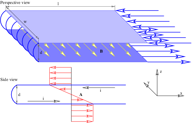
We now show that a capacitor that is charging or discharging has a magnetic field between the plates. Figure 17.1.2: shows a parallel plate capacitor with a current i flowing into the left plate and out of the right plate. This current is necessarily accompanied by an electric field that is changing with time: Ex=q/(ϵ0S)=it/(ϵ0S). Such an electric field can be derived from a scalar potential that is a function of time: ϕ = -itx∕ (ϵ 0S ). However, the Lorenz condition
∂Ax∂x+∂Ay∂y+∂Az∂z+1c2∂ϕ∂t=0
demands that some component of the vector potential A be non-zero under these circumstances, since ∂ϕ/∂t is non-zero.
How much can we infer about the vector potential from the geometry of the capacitor and Equation ???? Substituting ϕ=−itx/(ϵ0S) into this equation results in
∂Ax∂x+∂Ay∂y+∂Az∂z=ixϵ0c2S
which suggests a number of different possibilities for A. For instance, A=(0,ixy/(ϵ0c2S),0) and A=[0,0,ixz(ϵ0c2S)] both satisfy Equation ???. However, neither of these trial choices is satisfactory by itself, as they are not consistent with the cylindrical symmetry of the capacitor about the x axis.
A choice of vector potential that is consistent with the shape of the capacitor and satisfies the Lorenz condition is obtained by combining these two trial solutions:
A=[0,ixy/(2ϵ0c2S),ixz/(2ϵ0c2S)]
This vector potential leads to the magnetic field
B=[0,−iz/(2ϵ0c2S),iy/(2ϵ0c2S)]
These fields are illustrated in the right-hand panel of Figure 17.1.2:.
Circulation of a Vector Field
We have already seen one example of the circulation of a vector field, though we didn’t label it as such. In chapter 15 we computed the work done on a charge by the electric field as it moves around a closed loop in the context of the electric generator and Faraday’s law. The work done per unit charge, or the EMF, is an example of the circulation of a field, in this case the electric field, ΓE. Faraday’s law can be restated as
ΓE=−dΦBdt( Faraday's law )
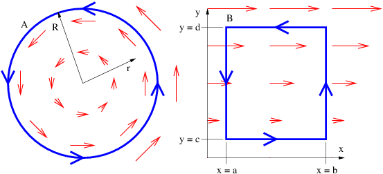
In the simple case of a circular loop with the field directed along the loop, the circulation is just the magnitude of the field multiplied by the circumference of the loop, as illustrated in the left panel of Figure 17.1.3:. In more complicated cases in which the field points in a direction other than the direction of the loop, just the component in the direction of traversal around the loop enters the circulation. If this component varies as one progresses around the loop, the calculation must be broken into pieces. The total circulation is then obtained by adding up the contributions from segments of the loop in which the value of the field component parallel to the motion around the loop is constant. An example of this type is the calculation of the EMF around a square loop of wire in an electric generator. Another is illustrated in the right panel of Figure 17.1.3:.

Ampère’s Law
The magnetic circulation ΓB around the periphery of the capacitor in the right panel of Figure 17.1.2: is easily computed by taking the magnitude of B in equation (???). The magnitude of the magnetic field on the inside of the capacitor is just B=ir/(2ϵ0c2 S), since r=(y2+z2)1/2 in Figure 17.1.2:. Thus, at the periphery of the capacitor, r=R, and B=iR/(2ϵ0c2S) there. The area of the capacitor plates is S=nR2 and ϵ0c2=1/μ0, as we discussed previously. Thus, the magnetic field is B=μ0i/(2πR) at the periphery. If the periphery is traversed in the counter-clockwise direction, the magnetic circulation around the capacitor is ΓB=2ΠRB=μ0i.
Let us now compute the magnetic circulation around a wire carrying a current. The magnetic field a distance r from a straight wire carrying a current i is B=μ0i/(2Πr). The magnetic field points in the direction of a circle concentric with the wire. The magnetic circulation around the wire is thus ΓB=2ΠrB=μ0i.
Notice that the magnetic circulation is found to be the same around the wire and around the periphery of the capacitor. Furthermore, this circulation depends only on the current in the wire and the constant μ0.
One further item needs to be calculated, namely the electric flux across the gap between the capacitor plates. This is just the electric field E=σ/ϵ0 multiplied by the area S, or ΦE=Sσ/ϵ0=q/ϵ0. The current into the capacitor is the time rate of change on the capacitor, so i=dq/dt=ϵ0 dΦE/dt.
We are now in a position to understand Ampère’s law:
ΓB=μ0(i+ϵ0dΦEdt)( Ampère's law ).
This states that the magnetic circulation around a loop equals the sum of two contributions, (1) μ 0 multiplied by the electric current through the loop and (2) μ 0ϵ 0 multiplied by the time rate of change of the electric flux through the loop. In the above example the first term dominates when the loop is around the wire, while the second term acts when the loop is around the gap between the capacitor plates.
Ampère actually formulated an incomplete version of the law named after him — he included only the first term containing the current. The Scottish physicist James Clerk Maxwell added the second term, based primarily on theoretical reasoning. Maxwell’s additional term solved a serious internal inconsistency in electromagnetic theory — in our terms, the Lorenz condition requires a magnetic field to exist if the scalar potential ϕ is time-dependent. This magnetic field is only predicted by Ampère’s law if Maxwell’s term is included. The quantity ϵ0dΦE/dt was called the displacement current by Maxwell since it has the dimensions of current and is numerically equal to the current entering the capacitor. However, it isn’t really a current — it is just an electric flux that changes with time!

Gauss’s law for electricity and magnetism, Faraday’s law, and Ampère’s law are collectively called Maxwell’s equations. Together they form the basis for electromagnetism as it developed historically. However, our formulation of electromagnetism in terms of the four-potential, the dispersion relation for free electromagnetic waves, the Lorenz condition, and Coulomb’s law, is precisely equivalent to Maxwell’s equations, and is much closer to the modern approach to electromagnetism.


