Physics LibreTexts

16.6: Interference of Waves

  • Page ID
    4073
  • \( \newcommand{\vecs}[1]{\overset { \scriptstyle \rightharpoonup} {\mathbf{#1}} } \)

    \( \newcommand{\vecd}[1]{\overset{-\!-\!\rightharpoonup}{\vphantom{a}\smash {#1}}} \)

    \( \newcommand{\id}{\mathrm{id}}\) \( \newcommand{\Span}{\mathrm{span}}\)

    ( \newcommand{\kernel}{\mathrm{null}\,}\) \( \newcommand{\range}{\mathrm{range}\,}\)

    \( \newcommand{\RealPart}{\mathrm{Re}}\) \( \newcommand{\ImaginaryPart}{\mathrm{Im}}\)

    \( \newcommand{\Argument}{\mathrm{Arg}}\) \( \newcommand{\norm}[1]{\| #1 \|}\)

    \( \newcommand{\inner}[2]{\langle #1, #2 \rangle}\)

    \( \newcommand{\Span}{\mathrm{span}}\)

    \( \newcommand{\id}{\mathrm{id}}\)

    \( \newcommand{\Span}{\mathrm{span}}\)

    \( \newcommand{\kernel}{\mathrm{null}\,}\)

    \( \newcommand{\range}{\mathrm{range}\,}\)

    \( \newcommand{\RealPart}{\mathrm{Re}}\)

    \( \newcommand{\ImaginaryPart}{\mathrm{Im}}\)

    \( \newcommand{\Argument}{\mathrm{Arg}}\)

    \( \newcommand{\norm}[1]{\| #1 \|}\)

    \( \newcommand{\inner}[2]{\langle #1, #2 \rangle}\)

    \( \newcommand{\Span}{\mathrm{span}}\) \( \newcommand{\AA}{\unicode[.8,0]{x212B}}\)

    \( \newcommand{\vectorA}[1]{\vec{#1}}      % arrow\)

    \( \newcommand{\vectorAt}[1]{\vec{\text{#1}}}      % arrow\)

    \( \newcommand{\vectorB}[1]{\overset { \scriptstyle \rightharpoonup} {\mathbf{#1}} } \)

    \( \newcommand{\vectorC}[1]{\textbf{#1}} \)

    \( \newcommand{\vectorD}[1]{\overrightarrow{#1}} \)

    \( \newcommand{\vectorDt}[1]{\overrightarrow{\text{#1}}} \)

    \( \newcommand{\vectE}[1]{\overset{-\!-\!\rightharpoonup}{\vphantom{a}\smash{\mathbf {#1}}}} \)

    \( \newcommand{\vecs}[1]{\overset { \scriptstyle \rightharpoonup} {\mathbf{#1}} } \)

    \( \newcommand{\vecd}[1]{\overset{-\!-\!\rightharpoonup}{\vphantom{a}\smash {#1}}} \)

    \(\newcommand{\avec}{\mathbf a}\) \(\newcommand{\bvec}{\mathbf b}\) \(\newcommand{\cvec}{\mathbf c}\) \(\newcommand{\dvec}{\mathbf d}\) \(\newcommand{\dtil}{\widetilde{\mathbf d}}\) \(\newcommand{\evec}{\mathbf e}\) \(\newcommand{\fvec}{\mathbf f}\) \(\newcommand{\nvec}{\mathbf n}\) \(\newcommand{\pvec}{\mathbf p}\) \(\newcommand{\qvec}{\mathbf q}\) \(\newcommand{\svec}{\mathbf s}\) \(\newcommand{\tvec}{\mathbf t}\) \(\newcommand{\uvec}{\mathbf u}\) \(\newcommand{\vvec}{\mathbf v}\) \(\newcommand{\wvec}{\mathbf w}\) \(\newcommand{\xvec}{\mathbf x}\) \(\newcommand{\yvec}{\mathbf y}\) \(\newcommand{\zvec}{\mathbf z}\) \(\newcommand{\rvec}{\mathbf r}\) \(\newcommand{\mvec}{\mathbf m}\) \(\newcommand{\zerovec}{\mathbf 0}\) \(\newcommand{\onevec}{\mathbf 1}\) \(\newcommand{\real}{\mathbb R}\) \(\newcommand{\twovec}[2]{\left[\begin{array}{r}#1 \\ #2 \end{array}\right]}\) \(\newcommand{\ctwovec}[2]{\left[\begin{array}{c}#1 \\ #2 \end{array}\right]}\) \(\newcommand{\threevec}[3]{\left[\begin{array}{r}#1 \\ #2 \\ #3 \end{array}\right]}\) \(\newcommand{\cthreevec}[3]{\left[\begin{array}{c}#1 \\ #2 \\ #3 \end{array}\right]}\) \(\newcommand{\fourvec}[4]{\left[\begin{array}{r}#1 \\ #2 \\ #3 \\ #4 \end{array}\right]}\) \(\newcommand{\cfourvec}[4]{\left[\begin{array}{c}#1 \\ #2 \\ #3 \\ #4 \end{array}\right]}\) \(\newcommand{\fivevec}[5]{\left[\begin{array}{r}#1 \\ #2 \\ #3 \\ #4 \\ #5 \\ \end{array}\right]}\) \(\newcommand{\cfivevec}[5]{\left[\begin{array}{c}#1 \\ #2 \\ #3 \\ #4 \\ #5 \\ \end{array}\right]}\) \(\newcommand{\mattwo}[4]{\left[\begin{array}{rr}#1 \amp #2 \\ #3 \amp #4 \\ \end{array}\right]}\) \(\newcommand{\laspan}[1]{\text{Span}\{#1\}}\) \(\newcommand{\bcal}{\cal B}\) \(\newcommand{\ccal}{\cal C}\) \(\newcommand{\scal}{\cal S}\) \(\newcommand{\wcal}{\cal W}\) \(\newcommand{\ecal}{\cal E}\) \(\newcommand{\coords}[2]{\left\{#1\right\}_{#2}}\) \(\newcommand{\gray}[1]{\color{gray}{#1}}\) \(\newcommand{\lgray}[1]{\color{lightgray}{#1}}\) \(\newcommand{\rank}{\operatorname{rank}}\) \(\newcommand{\row}{\text{Row}}\) \(\newcommand{\col}{\text{Col}}\) \(\renewcommand{\row}{\text{Row}}\) \(\newcommand{\nul}{\text{Nul}}\) \(\newcommand{\var}{\text{Var}}\) \(\newcommand{\corr}{\text{corr}}\) \(\newcommand{\len}[1]{\left|#1\right|}\) \(\newcommand{\bbar}{\overline{\bvec}}\) \(\newcommand{\bhat}{\widehat{\bvec}}\) \(\newcommand{\bperp}{\bvec^\perp}\) \(\newcommand{\xhat}{\widehat{\xvec}}\) \(\newcommand{\vhat}{\widehat{\vvec}}\) \(\newcommand{\uhat}{\widehat{\uvec}}\) \(\newcommand{\what}{\widehat{\wvec}}\) \(\newcommand{\Sighat}{\widehat{\Sigma}}\) \(\newcommand{\lt}{<}\) \(\newcommand{\gt}{>}\) \(\newcommand{\amp}{&}\) \(\definecolor{fillinmathshade}{gray}{0.9}\)
    Learning Objectives
    • Explain how mechanical waves are reflected and transmitted at the boundaries of a medium
    • Define the terms interference and superposition
    • Find the resultant wave of two identical sinusoidal waves that differ only by a phase shift

    Up to now, we have been studying mechanical waves that propagate continuously through a medium, but we have not discussed what happens when waves encounter the boundary of the medium or what happens when a wave encounters another wave propagating through the same medium. Waves do interact with boundaries of the medium, and all or part of the wave can be reflected. For example, when you stand some distance from a rigid cliff face and yell, you can hear the sound waves reflect off the rigid surface as an echo. Waves can also interact with other waves propagating in the same medium. If you throw two rocks into a pond some distance from one another, the circular ripples that result from the two stones seem to pass through one another as they propagate out from where the stones entered the water. This phenomenon is known as interference. In this section, we examine what happens to waves encountering a boundary of a medium or another wave propagating in the same medium. We will see that their behavior is quite different from the behavior of particles and rigid bodies. Later, when we study modern physics, we will see that only at the scale of atoms do we see similarities in the properties of waves and particles.

    Reflection and Transmission

    When a wave propagates through a medium, it reflects when it encounters the boundary of the medium. The wave before hitting the boundary is known as the incident wave. The wave after encountering the boundary is known as the reflected wave. How the wave is reflected at the boundary of the medium depends on the boundary conditions; waves will react differently if the boundary of the medium is fixed in place or free to move (Figure \(\PageIndex{1}\)). A fixed boundary condition exists when the medium at a boundary is fixed in place so it cannot move. A free boundary condition exists when the medium at the boundary is free to move.
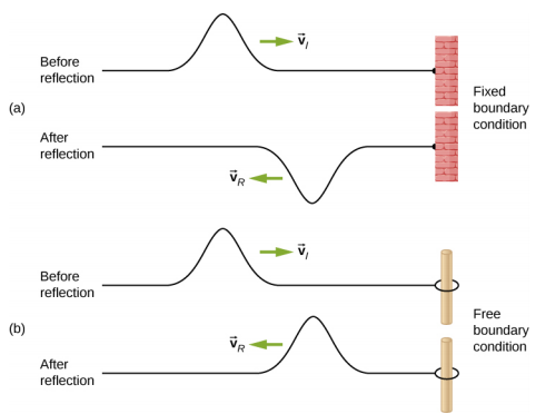
    Figure a shows two figures of a string attached to a rigid support at the right. The top string is labeled before reflection. A pulse formed at the top of the string propagates towards the right with velocity v subscript i. The bottom string is labeled after reflection. A pulse formed at the bottom of the string propagates towards the left with velocity v subscript R. Figure b shows two figures of a string attached to a ring that is passed through a pole on the right. The top string is labeled before reflection. A pulse formed at the top of the string propagates towards the right with velocity v subscript i. The bottom string is labeled after reflection. A pulse formed at the top of the string propagates towards the left with velocity v subscript R.
    Figure \(\PageIndex{1}\): (a) One end of a string is fixed so that it cannot move. A wave propagating on the string, encountering this fixed boundary condition, is reflected 180°(\(\pi\) rad) out of phase with respect to the incident wave. (b) One end of a string is tied to a solid ring of negligible mass on a frictionless lab pole, where the ring is free to move. A wave propagating on the string, encountering this free boundary condition, is reflected in phase 0°(0 rad) with respect to the wave.

    Figure \(\PageIndex{1a}\) shows a fixed boundary condition. Here, one end of the string is fixed to a wall so the end of the string is fixed in place and the medium (the string) at the boundary cannot move. When the wave is reflected, the amplitude of the reflected way is exactly the same as the amplitude of the incident wave, but the reflected wave is reflected \(180^o \pi\) rad) out of phase with respect to the incident wave. The phase change can be explained using Newton’s third law: Recall that Newton’s third law states that when object A exerts a force on object B, then object B exerts an equal and opposite force on object A. As the incident wave encounters the wall, the string exerts an upward force on the wall and the wall reacts by exerting an equal and opposite force on the string. The reflection at a fixed boundary is inverted. Note that the figure shows a crest of the incident wave reflected as a trough. If the incident wave were a trough, the reflected wave would be a crest.

    Figure \(\PageIndex{1b}\) shows a free boundary condition. Here, one end of the string is tied to a solid ring of negligible mass on a frictionless pole, so the end of the string is free to move up and down. As the incident wave encounters the boundary of the medium, it is also reflected. In the case of a free boundary condition, the reflected wave is in phase with respect to the incident wave. In this case, the wave encounters the free boundary applying an upward force on the ring, accelerating the ring up. The ring travels up to the maximum height equal to the amplitude of the wave and then accelerates down towards the equilibrium position due to the tension in the string. The figure shows the crest of an incident wave being reflected in phase with respect to the incident wave as a crest. If the incident wave were a trough, the reflected wave would also be a trough. The amplitude of the reflected wave would be equal to the amplitude of the incident wave.

    In some situations, the boundary of the medium is neither fixed nor free. Consider Figure \(\PageIndex{2a}\), where a low-linear mass density string is attached to a string of a higher linear mass density. In this case, the reflected wave is out of phase with respect to the incident wave. There is also a transmitted wave that is in phase with respect to the incident wave. Both the transmitted and reflected waves have amplitudes less than the amplitude of the incident wave. If the tension is the same in both strings, the wave speed is higher in the string with the lower linear mass density.
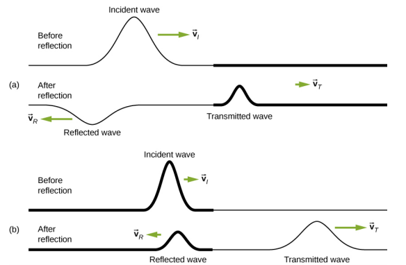
    Figure a shows two strings, the top one labeled before reflection and the bottom one labeled after reflection. The top string has a pulse labeled incident wave, which propagates to the right with velocity v subscript i. The bottom string has two pulses. The one on the left is labeled transmitted wave. This propagates to the right with velocity v subscript T. The wave on the left is labeled reflected wave. It moves to the left with velocity v subscript R. It has a smaller amplitude from the incident wave and is upside down. Figure b shows two strings, the top one labeled before reflection and the bottom one labeled after reflection. The top string has a pulse labeled incident wave, which propagates to the right with velocity v subscript i. The bottom string has two pulses. The one on the left is labeled transmitted wave and the one on the right is labeled reflected wave. Both are formed at the top of the string.
    Figure \(\PageIndex{2}\): Waves traveling along two types of strings: a thick string with a high linear density and a thin string with a low linear density. Both strings are under the same tension, so a wave moves faster on the low-density string than on the high-density string. (a) A wave moving from a low-speed to a high-speed medium results in a reflected wave that is 180°(\(\pi\) rad) out of phase with respect to the incident pulse (or wave) and a transmitted wave that is in phase with the incident wave. (b) When a wave moves from a low-speed medium to a high-speed medium, both the reflected and transmitted wave are in phase with respect to the incident wave.

    \(\PageIndex{2b}\) shows a high-linear mass density string is attached to a string of a lower linear density. In this case, the reflected wave is in phase with respect to the incident wave. There is also a transmitted wave that is in phase with respect to the incident wave. Both the incident and the reflected waves have amplitudes less than the amplitude of the incident wave. Here you may notice that if the tension is the same in both strings, the wave speed is higher in the string with the lower linear mass density.

    Superposition and Interference

    Most waves do not look very simple. Complex waves are more interesting, even beautiful, but they look formidable. Most interesting mechanical waves consist of a combination of two or more traveling waves propagating in the same medium. The principle of superposition can be used to analyze the combination of waves.

    Consider two simple pulses of the same amplitude moving toward one another in the same medium, as shown in Figure \(\PageIndex{3}\). Eventually, the waves overlap, producing a wave that has twice the amplitude, and then continue on unaffected by the encounter. The pulses are said to interfere, and this phenomenon is known as interference.
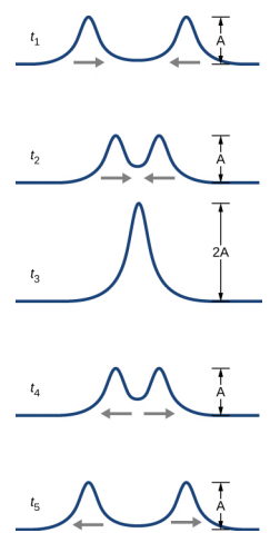
    Five figures show the different stages of two pulses moving towards each other. The pulses are far apart at time t1. Both have amplitude A. They move towards each other at time t2, combining into a wave with two peaks. At time t3, they combine into a single wave with amplitude 2A. At time t4, they move apart again, each regaining the amplitude A. They come back to their original positions at time t5.
    Figure \(\PageIndex{3}\): Two pulses moving toward one another experience interference. The term interference refers to what happens when two waves overlap.

    To analyze the interference of two or more waves, we use the principle of superposition. For mechanical waves, the principle of superposition states that if two or more traveling waves combine at the same point, the resulting position of the mass element of the medium, at that point, is the algebraic sum of the position due to the individual waves. This property is exhibited by many waves observed, such as waves on a string, sound waves, and surface water waves. Electromagnetic waves also obey the superposition principle, but the electric and magnetic fields of the combined wave are added instead of the displacement of the medium. Waves that obey the superposition principle are linear waves; waves that do not obey the superposition principle are said to be nonlinear waves. In this chapter, we deal with linear waves, in particular, sinusoidal waves.

    The superposition principle can be understood by considering the linear wave equation. In Mathematics of a Wave, we defined a linear wave as a wave whose mathematical representation obeys the linear wave equation. For a transverse wave on a string with an elastic restoring force, the linear wave equation is

    \[\frac{\partial^{2} y(x,t)}{\partial x^{2}} = \frac{1}{v^{2}} \frac{\partial^{2} y(x,t)}{\partial t^{2}} \ldotp\]

    Any wave function y(x, t) = y(x ∓ vt), where the argument of the function is linear (x ∓ vt) is a solution to the linear wave equation and is a linear wave function. If wave functions y1(x, t) and y2(x, t) are solutions to the linear wave equation, the sum of the two functions y1(x, t) + y2(x, t) is also a solution to the linear wave equation. Mechanical waves that obey superposition are normally restricted to waves with amplitudes that are small with respect to their wavelengths. If the amplitude is too large, the medium is distorted past the region where the restoring force of the medium is linear.

    Waves can interfere constructively or destructively. Figure \(\PageIndex{4}\) shows two identical sinusoidal waves that arrive at the same point exactly in phase. Figure \(\PageIndex{4a}\) and \(\PageIndex{4b}\) show the two individual waves, Figure \(\PageIndex{4c}\) shows the resultant wave that results from the algebraic sum of the two linear waves. The crests of the two waves are precisely aligned, as are the troughs. This superposition produces constructive interference. Because the disturbances add, constructive interference produces a wave that has twice the amplitude of the individual waves, but has the same wavelength.
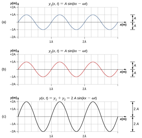
    Figures a and b each show a wave with amplitude A and wavelength lambda. They are in phase with one another. Figure a is labeled y1 parentheses x, t parentheses equal to A sine parentheses kx minus omega t parentheses. Figure b is labeled y2 parentheses x, t parentheses equal to A sine parentheses kx minus omega t parentheses. Figure c shows a wave that is in phase with the other two. It has amplitude 2A and wavelength lambda. It is labeled y parentheses x, t parentheses equal to y1 plus y2 equal to 2A sine parentheses kx minus omega t parentheses.
    Figure \(\PageIndex{4}\): Constructive interference of two identical waves produces a wave with twice the amplitude, but the same wavelength.

    Figure \(\PageIndex{5}\) shows two identical waves that arrive exactly 180° out of phase, producing destructive interference. Figure \(\PageIndex{5a}\) and \(\PageIndex{5b}\) show the individual waves, and Figure \(\PageIndex{5c}\) shows the superposition of the two waves. Because the troughs of one wave add the crest of the other wave, the resulting amplitude is zero for destructive interference—the waves completely cancel.
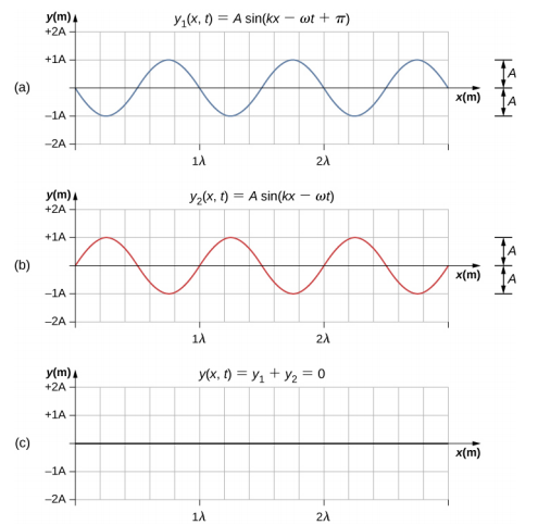
    Figures a and b each show a wave with amplitude A and wavelength lambda. They are out of phase with one another by an angle pi. Figure a is labeled y1 parentheses x, t parentheses equal to A sine parentheses kx minus omega t plus pi parentheses. Figure b is labeled y2 parentheses x, t parentheses equal to A sine parentheses kx minus omega t parentheses. Figure c shows the absence of any wave. It is labeled y parentheses x, t parentheses equal to y1 plus y2 equal to 0.
    Figure \(\PageIndex{5}\): Destructive interference of two identical waves, one with a phase shift of 180°(\(\pi\) rad), produces zero amplitude, or complete cancellation.

    When linear waves interfere, the resultant wave is just the algebraic sum of the individual waves as stated in the principle of superposition. Figure \(\PageIndex{6}\) shows two waves (red and blue) and the resultant wave (black). The resultant wave is the algebraic sum of the two individual waves.
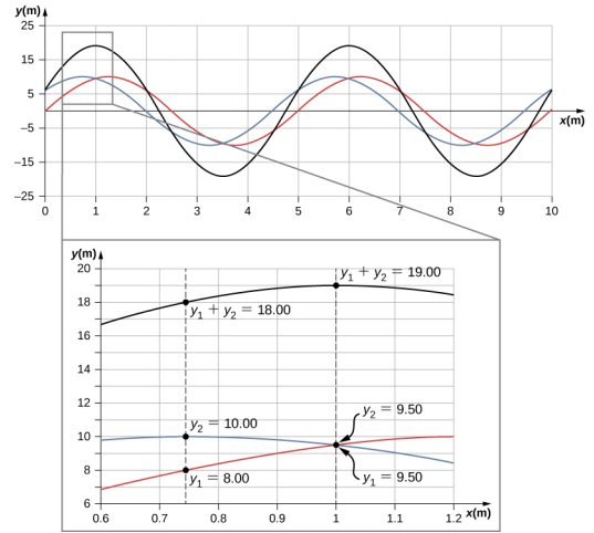
    Figure shows three waves. Two of these, blue and red have y values varying from -10 to plus 10 and the same wavelength. They are slightly out of phase. The third, which is black, has the same wavelength but a larger amplitude. Another figure shows a blown up portion of this graph. At x approximately equal to 0.74, the y values of the red and blue waves are y1 = 8 and y2 = 10 respectively. The y value of the black wave is y1 + y2 = 18. At x equal to 1, the y values of the red and blue waves are both 9.5. The y value of the black wave is y1 + y2 = 19.
    Figure \(\PageIndex{6}\): When two linear waves in the same medium interfere, the height of resulting wave is the sum of the heights of the individual waves, taken point by point. This plot shows two waves (red and blue) added together, along with the resulting wave (black). These graphs represent the height of the wave at each point. The waves may be any linear wave, including ripples on a pond, disturbances on a string, sound, or electromagnetic waves.

    The superposition of most waves produces a combination of constructive and destructive interference, and can vary from place to place and time to time. Sound from a stereo, for example, can be loud in one spot and quiet in another. Varying loudness means the sound waves add partially constructively and partially destructively at different locations. A stereo has at least two speakers creating sound waves, and waves can reflect from walls. All these waves interfere, and the resulting wave is the superposition of the waves.

    We have shown several examples of the superposition of waves that are similar. Figure \(\PageIndex{7}\) illustrates an example of the superposition of two dissimilar waves. Here again, the disturbances add, producing a resultant wave.
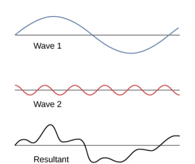
    Figure shows three waves. Wave 1 has larger wavelength and amplitude compared to wave 2. The third wave, labeled resultant wave is irregularly shaped.
    Figure \(\PageIndex{7}\): Superposition of nonidentical waves exhibits both constructive and destructive interference.

    At times, when two or more mechanical waves interfere, the pattern produced by the resulting wave can be rich in complexity, some without any readily discernable patterns. For example, plotting the sound wave of your favorite music can look quite complex and is the superposition of the individual sound waves from many instruments; it is the complexity that makes the music interesting and worth listening to. At other times, waves can interfere and produce interesting phenomena, which are complex in their appearance and yet beautiful in simplicity of the physical principle of superposition, which formed the resulting wave. One example is the phenomenon known as standing waves, produced by two identical waves moving in different directions. We will look more closely at this phenomenon in the next section.

    Simulation

    Try this simulation to make waves with a dripping faucet, audio speaker, or laser! Add a second source or a pair of slits to create an interference pattern. You can observe one source or two sources. Using two sources, you can observe the interference patterns that result from varying the frequencies and the amplitudes of the sources.

    Superposition of Sinusoidal Waves that Differ by a Phase Shift

    Many examples in physics consist of two sinusoidal waves that are identical in amplitude, wave number, and angular frequency, but differ by a phase shift:

    \[\begin{split} y_{1} (x,t) & = A \sin (kx - \omega t + \phi), \\ y_{2} (x,t) & = A \sin (kx - \omega t) \ldotp \end{split}\]

    When these two waves exist in the same medium, the resultant wave resulting from the superposition of the two individual waves is the sum of the two individual waves:

    \[y_{R} (x,t) = y_{1} (x,t) + y_{2} (x,t) = A \sin(kx - \omega t + \phi) + A \sin (kx - \omega t) \ldotp\]

    The resultant wave can be better understood by using the trigonometric identity:

    \[\sin u + \sin v = 2 \sin \left(\dfrac{u + v}{2}\right) \cos \left(\dfrac{u - v}{2}\right),\]

    where u = kx - \(\omega\)t + \(\phi\) and v = kx - \(\omega\)t. The resulting wave becomes

    \[\begin{split} y_{R} (x,t) & = y_{1} (x,t) + y_{2} (x,t) = A \sin (kx - \omega t + \phi) + A \sin (kx - \omega t) \\ & = 2A \sin \left(\dfrac{(kx - \omega t + \phi) + (kx - \omega t)}{2}\right) \cos \left(\dfrac{(kx - \omega t + \phi) - (kx - \omega t)}{2}\right) \\ & = 2A \sin \left(kx - \omega t + \dfrac{\phi}{2}\right) \cos \left(\dfrac{\phi}{2}\right) \ldotp \end{split}\]

    This equation is usually written as

    \[y_{R} (x,t) = 2A \cos \left(\dfrac{\phi}{2}\right) \sin \left(kx - \omega t + \dfrac{\phi}{2}\right) \ldotp \label{16.13}\]

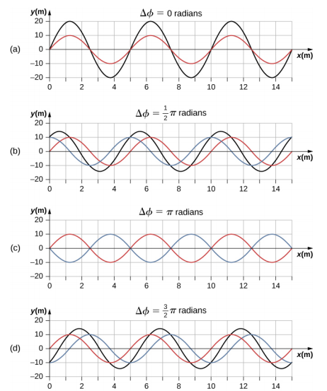
    The resultant wave has the same wave number and angular frequency, an amplitude of AR = [2A cos\(\left(\dfrac{\phi}{2}\right)\)], and a phase shift equal to half the original phase shift. Examples of waves that differ only in a phase shift are shown in Figure \(\PageIndex{7}\).

    radians. The crests of the blue wave coincide with the troughs of the red wave and vice versa. The green wave is absent. Figure d is labeled delta phi equal to 3 pi by 2 radians. Here, the red and blue waves each have an amplitude of 10 m and the green wave has an amplitude of 15 m. It has the same wavelength as the other two waves. The crests of the green wave are formed where the crests of the red and blue waves intersect each other.
    Figure \(\PageIndex{8}\): Superposition of two waves with identical amplitudes, wavelengths, and frequency, but that differ in a phase shift. The red wave is defined by the wave function y1(x, t) = A sin(kx − \(\omega\)t) and the blue wave is defined by the wave function y2(x, t) = A sin(kx − \(\omega\)t + \(\phi\)). The black line shows the result of adding the two waves. The phase difference between the two waves are (a) 0.00 rad, (b) \(\frac{\pi}{2}\) rad, (c) \(\pi\) rad, and (d) \(\frac{3 \pi}{2}\) rad.

    The red and blue waves each have the same amplitude, wave number, and angular frequency, and differ only in a phase shift. They therefore have the same period, wavelength, and frequency. The green wave is the result of the superposition of the two waves. When the two waves have a phase difference of zero, the waves are in phase, and the resultant wave has the same wave number and angular frequency, and an amplitude equal to twice the individual amplitudes (part (a)). This is constructive interference. If the phase difference is 180°, the waves interfere in destructive interference (part (c)). The resultant wave has an amplitude of zero. Any other phase difference results in a wave with the same wave number and angular frequency as the two incident waves but with a phase shift of \(\frac{\phi}{2}\) and an amplitude equal to 2A cos\(\left(\dfrac{\phi}{2}\right)\). Examples are shown in parts (b) and (d).


    This page titled 16.6: Interference of Waves is shared under a CC BY 4.0 license and was authored, remixed, and/or curated by OpenStax via source content that was edited to the style and standards of the LibreTexts platform.