17.5: Normal Modes of a Standing Sound Wave
- Page ID
- 4079
- Explain the mechanism behind sound-reducing headphones
- Describe resonance in a tube closed at one end and open at the other end
- Describe resonance in a tube open at both ends
Interference is the hallmark of waves, all of which exhibit constructive and destructive interference exactly analogous to that seen for water waves. In fact, one way to prove something “is a wave” is to observe interference effects. Since sound is a wave, we expect it to exhibit interference.
Interference of Sound Waves
In waves, we discussed the interference of wave functions that differ only in a phase shift. We found that the wave function resulting from the superposition of \(y_{1}(x, t)=A \sin (k x-\omega t+\phi)\) and \(y_{2}(x, t)=A \sin (k x-\omega t)\) is
\[ y(x, t)=\left[2 A \cos \left(\frac{\phi}{2}\right)\right] \sin \left(k x-\omega t+\frac{\phi}{2}\right). \nonumber \]
One way for two identical waves that are initially in phase to become out of phase with one another is to have the waves travel different distances; that is, they have different path lengths. Sound waves provide an excellent example of a phase shift due to a path difference. As we have discussed, sound waves can basically be modeled as longitudinal waves, where the molecules of the medium oscillate around an equilibrium position, or as pressure waves.
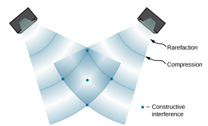
When the waves leave the speakers, they move out as spherical waves (Figure \(\PageIndex{1}\)). The waves interfere; constructive inference is produced by the combination of two crests or two troughs, as shown. Destructive interference is produced by the combination of a trough and a crest.
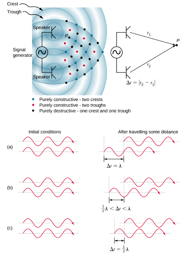
The phase difference at each point is due to the different path lengths traveled by each wave. When the difference in the path lengths is an integer multiple of a wavelength,
\[ \Delta r=\left|r_{2}-r_{1}\right|=n \lambda, \text { where } n=0,1,2,3, \ldots \nonumber \]
the waves are in phase and there is constructive interference. When the difference in path lengths is an odd multiple of a half wavelength,
\[ \Delta r=\left|r_{2}-r_{1}\right|=n \frac{\lambda}{2}, \text { where } n=1,3,5, \ldots \nonumber \]
the waves are 180°(\(\pi\) rad) out of phase and the result is destructive interference. These points can be located with a sound-level intensity meter.
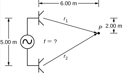
Two speakers are separated by 5.00 m and are being driven by a signal generator at an unknown frequency. A student with a sound-level meter walks out 6.00 m and down 2.00 m, and finds the first minimum intensity, as shown below. What is the frequency supplied by the signal generator? Assume the wave speed of sound is v = 343.00m/s.
Strategy
The wave velocity is equal to \(v = \frac{\lambda}{T} = \lambda f\). The frequency is then \(f = \frac{v}{\lambda}\). A minimum intensity indicates destructive interference and the first such point occurs where there is path difference of \(\Delta r = \lambda / 2\), which can be found from the geometry.
Solution
1. Find the path length to the minimum point from each speaker
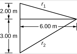
\[ r_{1}=\sqrt{(6.00 \: \mathrm{m})^{2}+(2.00 \: \mathrm{m})^{2}}=6.32 \: \mathrm{m}, r_{2}=\sqrt{(6.00 \: \mathrm{m})^{2}+(3.00 \: \mathrm{m})^{2}}=6.71 \: \mathrm{m} \nonumber \]
2. Use the difference in the path length to find the wavelength.
\begin{array}{c}
\Delta r=\left|r_{2}-r_{1}\right|=|6.71 \: \mathrm{m}-6.32 \: \mathrm{m}|=0.39 \: \mathrm{m} \nonumber \\
\lambda=2 \Delta r=2(0.39 \: \mathrm{m})=0.78 \: \mathrm{m} \nonumber
\end{array}
3. Find the frequency.
\[ f=\frac{v}{\lambda}=\frac{343.00 \: \mathrm{m} / \mathrm{s}}{0.78 \: \mathrm{m}}=439.74 \: \mathrm{Hz} \nonumber \]
Significance
If point P were a point of maximum intensity, then the path length would be an integer multiple of the wavelength.
If you walk around two speakers playing music, how come you do not notice places where the music is very loud or very soft, that is, where there is constructive and destructive interference?
The concept of a phase shift due to a difference in path length is very important. You will use this concept again in Interference and Photons and Matter Waves, where we discuss how Thomas Young used this method in his famous double-slit experiment to provide evidence that light has wavelike properties.
Noise Reduction Through Destructive Interference
Figure \(\PageIndex{3}\) shows a clever use of sound interference to cancel noise. Larger-scale applications of active noise reduction by destructive interference have been proposed for entire passenger compartments in commercial aircraft. To obtain destructive interference, a fast electronic analysis is performed, and a second sound is introduced 180° out of phase with the original sound, with its maxima and minima exactly reversed from the incoming noise. Sound waves in fluids are pressure waves and are consistent with Pascal’s principle; that is, pressures from two different sources add and subtract like simple numbers. Therefore, positive and negative gauge pressures add to a much smaller pressure, producing a lower-intensity sound. Although completely destructive interference is possible only under the simplest conditions, it is possible to reduce noise levels by 30 dB or more using this technique.
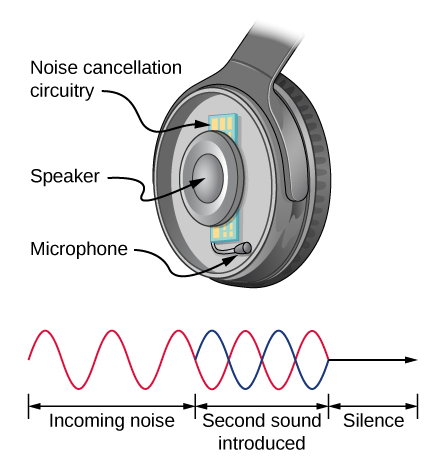
Describe how noise-canceling headphones differ from standard headphones used to block outside sounds.
Where else can we observe sound interference? All sound resonances, such as in musical instruments, are due to constructive and destructive interference. Only the resonant frequencies interfere constructively to form standing waves, whereas others interfere destructively and are absent.
Resonance in a Tube Closed at One End
As we discussed in Waves, standing waves are formed by two waves moving in opposite directions. When two identical sinusoidal waves move in opposite directions, the waves may be modeled as
\[ y_{1}(x, t)=A \sin (k x-\omega t) \text { and } y_{2}(x, t)=A \sin (k x+\omega t) \nonumber .\]
When these two waves interference, the resultant wave is a standing wave:
\[ y_{\mathrm{R}}(x, t)=[2 A \sin (k x)] \cos (\omega t) . \nonumber \]
Resonance can be produced due to the boundary conditions imposed on a wave. In Waves, we showed that resonance could be produced in a string under tension that had symmetrical boundary conditions, specifically, a node at each end. We defined a node as a fixed point where the string did not move. We found that the symmetrical boundary conditions resulted in some frequencies resonating and producing standing waves, while other frequencies interfere destructively. Sound waves can resonate in a hollow tube, and the frequencies of the sound waves that resonate depend on the boundary conditions.
Suppose we have a tube that is closed at one end and open at the other. If we hold a vibrating tuning fork near the open end of the tube, an incident sound wave travels through the tube and reflects off the closed end. The reflected sound has the same frequency and wavelength as the incident sound wave, but is traveling in the opposite direction. At the closed end of the tube, the molecules of air have very little freedom to oscillate, and a node arises. At the open end, the molecules are free to move, and at the right frequency, an antinode occurs. Unlike the symmetrical boundary conditions for the standing waves on the string, the boundary conditions for a tube open at one end and closed at the other end are anti-symmetrical: a node at the closed end and an antinode at the open end.
If the tuning fork has just the right frequency, the air column in the tube resonates loudly, but at most frequencies it vibrates very little. This observation just means that the air column has only certain natural frequencies. Consider the lowest frequency that will cause the tube to resonate, producing a loud sound. There will be a node at the closed end and an antinode at the open end, as shown in Figure \(\PageIndex{4}\).
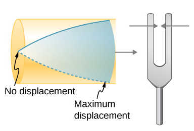
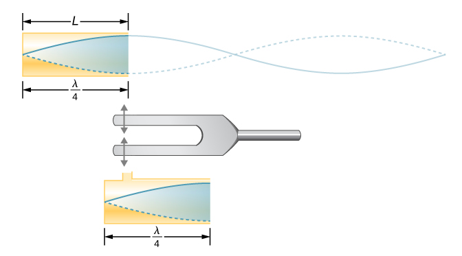
The standing wave formed in the tube has an antinode at the open end and a node at the closed end. The distance from a node to an antinode is one-fourth of a wavelength, and this equals the length of the tube; thus, \(\lambda_1 = 4L\). This same resonance can be produced by a vibration introduced at or near the closed end of the tube (Figure \(\PageIndex{5}\)). It is best to consider this a natural vibration of the air column, independently of how it is induced.
Given that maximum air displacements are possible at the open end and none at the closed end, other shorter wavelengths can resonate in the tube, such as the one shown in Figure \(\PageIndex{6}\). Here the standing wave has three-fourths of its wavelength in the tube, or \(\frac{3}{4} \lambda_3 = L\), so that \(\lambda_3 = \frac{4}{3} L\). Continuing this process reveals a whole series of shorter-wavelength and higher-frequency sounds that resonate in the tube. We use specific terms for the resonances in any system. The lowest resonant frequency is called the fundamental, while all higher resonant frequencies are called overtones. The resonant frequencies that are integral multiples of the fundamental are collectively called harmonics. The fundamental is the first harmonic, the second harmonic is twice the frequency of the first harmonic, and so on. Some of these harmonics may not exist for a given scenario. Figure \(\PageIndex{7}\) shows the fundamental and the first three overtones (or the first, third, fifth, and seventh harmonics) in a tube closed at one end.
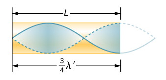

The relationship for the resonant wavelengths of a tube closed at one end is
\[\lambda_{n}=\frac{4}{n} L \quad n=1,3,5, \ldots \label{17.13} \]
Now let us look for a pattern in the resonant frequencies for a simple tube that is closed at one end. The fundamental has \(\lambda = 4L\), and frequency is related to wavelength and the speed of sound as given by
\[ v = f \lambda \nonumber .\]
Solving for \(f\) in this equation gives
\[ f=\frac{v}{\lambda}=\frac{v}{4 L}, \nonumber \]
where v is the speed of sound in air. Similarly, the first overtone has \(\lambda = 4L/3\) (see Figure \(\PageIndex{7}\)), so that
\[ f_{3}=3 \frac{v}{4 L}=3 f_{1} . \nonumber \]
Because \(f_3 = 3 f_1\), we call the first overtone the third harmonic. Continuing this process, we see a pattern that can be generalized in a single expression. The resonant frequencies of a tube closed at one end are
\[ f_{n}=n \frac{v}{4 L}, \quad n=1,3,5, \dots \label{17.14} \]
where \(f_1\) is the fundamental, \(f_3\) is the first overtone, and so on. It is interesting that the resonant frequencies depend on the speed of sound and, hence, on temperature. This dependence poses a noticeable problem for organs in old unheated cathedrals, and it is also the reason why musicians commonly bring their wind instruments to room temperature before playing them.
Resonance in a Tube Open at Both Ends
Another source of standing waves is a tube that is open at both ends. In this case, the boundary conditions are symmetrical: an antinode at each end. The resonances of tubes open at both ends can be analyzed in a very similar fashion to those for tubes closed at one end. The air columns in tubes open at both ends have maximum air displacements at both ends (Figure \(\PageIndex{8}\)). Standing waves form as shown.

The relationship for the resonant wavelengths of a tube open at both ends is
\[ \lambda_{n}=\frac{2}{n} L, \quad n=1,2,3, \ldots \label{17.15} \]
Based on the fact that a tube open at both ends has maximum air displacements at both ends, and using Figure \(\PageIndex{8}\) as a guide, we can see that the resonant frequencies of a tube open at both ends are
\[ f_{n}=n \frac{v}{2 L}, \quad n=1,2,3 \dots, \label{17.16} \]
where \(f_1\) is the fundamental, \(f_2\) is the first overtone, \(f_3\) is the second overtone, and so on. Note that a tube open at both ends has a fundamental frequency twice what it would have if closed at one end. It also has a different spectrum of overtones than a tube closed at one end.
Note that a tube open at both ends has symmetrical boundary conditions, similar to the string fixed at both ends discussed in Waves. The relationships for the wavelengths and frequencies of a stringed instrument are the same as given in Equation \ref{17.15} and Equation \ref{17.16}. The speed of the wave on the string (from Waves) is \(v = \sqrt{\frac{F_{T}}{\mu}}\). The air around the string vibrates at the same frequency as the string, producing sound of the same frequency. The sound wave moves at the speed of sound and the wavelength can be found using \(v = \lambda f\).
How is it possible to use a standing wave’s node and antinode to determine the length of a closed-end tube
This video lets you visualize sound waves.
You observe two musical instruments that you cannot identify. One plays high-pitched sounds and the other plays low-pitched sounds. How could you determine which is which without hearing either of them play?


