
2.4: Images Formed by Refraction


- Last updated
- Mar 26, 2025
- Save as PDF

( \newcommand{\kernel}{\mathrm{null}\,}\)
By the end of this section, you will be able to:
- Describe image formation by a single refracting surface
- Determine the location of an image and calculate its properties by using a ray diagram
- Determine the location of an image and calculate its properties by using the equation for a single refracting surface
When rays of light propagate from one medium to another, these rays undergo refraction, which is when light waves are bent at the interface between two media. The refracting surface can form an image in a similar fashion to a reflecting surface, except that the law of refraction (Snell’s law) is at the heart of the process instead of the law of reflection.
Refraction at a Plane Interface—Apparent Depth
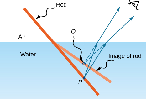
If you look at a straight rod partially submerged in water, it appears to bend at the surface. The reason behind this curious effect is that the image of the rod inside the water forms a little closer to the surface than the actual position of the rod, so it does not line up with the part of the rod that is above the water. The same phenomenon explains why a fish in water appears to be closer to the surface than it actually is.
To study image formation as a result of refraction, consider the following questions:
- What happens to the rays of light when they enter or pass through a different medium?
- Do the refracted rays originating from a single point meet at some point or diverge away from each other?
To be concrete, we consider a simple system consisting of two media separated by a plane interface (Figure \PageIndex{2}). The object is in one medium and the observer is in the other. For instance, when you look at a fish from above the water surface, the fish is in medium 1 (the water) with refractive index 1.33, and your eye is in medium 2 (the air) with refractive index 1.00, and the surface of the water is the interface. The depth that you “see” is the image height h_i and is called the apparent depth. The actual depth of the fish is the object height h_o.
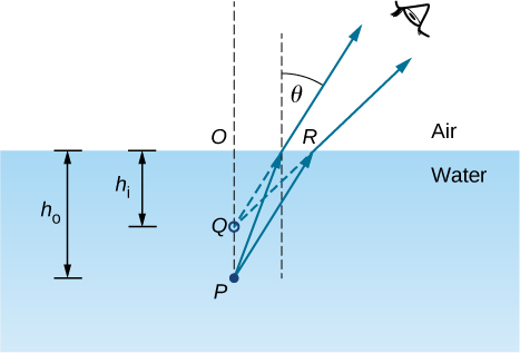
The apparent depth hi depends on the angle at which you view the image. For a view from above (the so-called “normal” view), we can approximate the refraction angle θ to be small, and replace \sin θ in Snell’s law by \tan θ. With this approximation, you can use the triangles ΔOPR and ΔOQR to show that the apparent depth is given by
h_i= \left(\dfrac{n_2}{n_1}\right)h_o. \nonumber
The derivation of this result is left as an exercise. Thus, a fish appears at 3/4 of the real depth when viewed from above.
Refraction at a Spherical Interface
Spherical shapes play an important role in optics primarily because high-quality spherical shapes are far easier to manufacture than other curved surfaces. To study refraction at a single spherical surface, we assume that the medium with the spherical surface at one end continues indefinitely (a “semi-infinite” medium).
Refraction at a Convex Surface
Consider a point source of light at point P in front of a convex surface made of glass (Figure \PageIndex{3}). Let R be the radius of curvature, n1 be the refractive index of the medium in which object point P is located, and n2 be the refractive index of the medium with the spherical surface. We want to know what happens as a result of refraction at this interface.

Because of the symmetry involved, it is sufficient to examine rays in only one plane. The figure shows a ray of light that starts at the object point P, refracts at the interface, and goes through the image point P′. We derive a formula relating the object distance d_o, the image distance d_i, and the radius of curvature R.
Applying Snell’s law to the ray emanating from point P gives
n_1\sin θ_1=n_2 \sin θ_2. \nonumber
Within the small-angle approximation
\sin θ≈θ, \nonumber
Snell’s law then takes the form
n_1θ_1≈n_2θ_2. \label{eq8}
From the geometry of Figure \PageIndex{3}, we see that
θ_1=α+ϕ, \nonumber
θ_2=ϕ−β. \nonumber
Inserting both expressions into Equation \ref{eq8} gives
n_1(α+ϕ)≈n_2(ϕ−β). \label{eq10}
Using Figure \PageIndex{3}, we calculate the tangent of the angles α, β, and ϕ:
- \tan α≈\dfrac{h}{d_o}
- \tan β≈\dfrac{h}{d_i}
- \tan ϕ≈\dfrac{h}{R}
Again using the small-angle approximation, we find that \tan θ≈ θ, so the above relationships become
- α≈\dfrac{h}{d_o}
- ~β≈\dfrac{h}{d_i}
- ~ϕ≈\dfrac{h}{R}.
Putting these angles into Equation \ref{eq10} gives
n_1\left(\dfrac{h}{d_o}+\dfrac{h}{R}\right)=n_2 \left(\dfrac{h}{R}−\dfrac{h}{d_i}\right). \nonumber
We can write this more conveniently as
\dfrac{n_1}{d_o}+\dfrac{n_2}{d_i}=\dfrac{n_2−n_1}{R}.
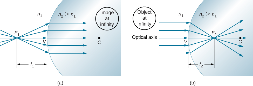
If the object is placed at a special point called the first focus, or the object focus F_1, then the image is formed at infinity, as shown in Figure \PageIndex{4a}.
We can find the location f_1 of the first focus F_1 by setting d_i=\infty in Equation \ref{eq20}.
\begin{align} \dfrac{n_1}{f_1}+\dfrac{n_2}{\infty} &=\dfrac{n_2−n_1}{R} \\[4pt] f_1 &=\dfrac{n_1R}{n_2−n_1} \end{align} \nonumber
Similarly, we can define a second focus or image focus F_2 where the image is formed for an object that is far away (Figure \PageIndex{4b}). The location of the second focus F_2 is obtained from Equation \ref{eq20} by setting d_0=\infty:
\begin{align} \dfrac{n_1}{\infty}+\dfrac{n_2}{f_2}=\dfrac{n_2−n_1}{R} \\[4pt] f_2=\dfrac{n_2R}{n_2−n_1}. \end{align} \nonumber
Note that the object focus is at a different distance from the vertex than the image focus because n_1≠n_2.
Although we derived this equation for refraction at a convex surface, the same expression holds for a concave surface, provided we use the following sign convention:
- R>0 if surface is convex toward object; otherwise, R<0.
- d_i>0 if image is real and on opposite side from the object; otherwise, d_i<0.