2.5: Thin Lenses
( \newcommand{\kernel}{\mathrm{null}\,}\)
By the end of this section, you will be able to:
- Use ray diagrams to locate and describe the image formed by a lens
- Employ the thin-lens equation to describe and locate the image formed by a lens
Lenses are found in a huge array of optical instruments, ranging from a simple magnifying glass to a camera’s zoom lens to the eye itself. In this section, we use the Snell’s law to explore the properties of lenses and how they form images.
The word “lens” derives from the Latin word for a lentil bean, the shape of which is similar to a convex lens. However, not all lenses have the same shape. Figure 2.5.1 shows a variety of different lens shapes. The vocabulary used to describe lenses is the same as that used for spherical mirrors: The axis of symmetry of a lens is called the optical axis, where this axis intersects the lens surface is called the vertex of the lens, and so forth.
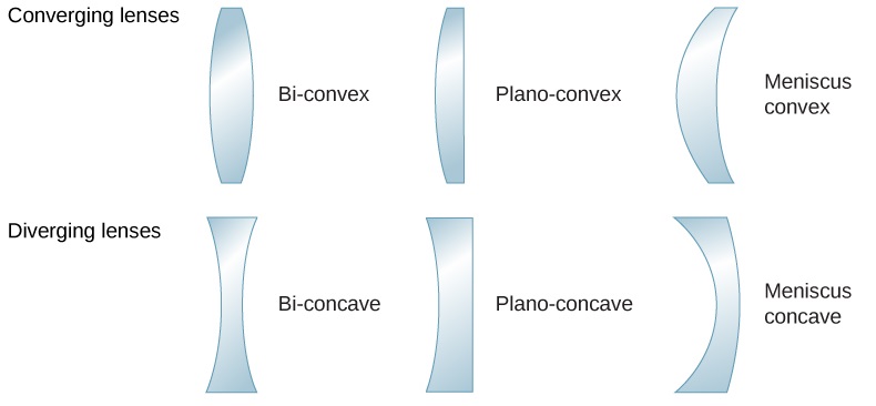
A convex or converging lens is shaped so that all light rays that enter it parallel to its optical axis intersect (or focus) at a single point on the optical axis on the opposite side of the lens, as shown in Figure 2.5.1a. Likewise, a concave or diverging lens is shaped so that all rays that enter it parallel to its optical axis diverge, as shown in part (b). To understand more precisely how a lens manipulates light, look closely at the top ray that goes through the converging lens in part (a). Because the index of refraction of the lens is greater than that of air, Snell’s law tells us that the ray is bent toward the perpendicular to the interface as it enters the lens. Likewise, when the ray exits the lens, it is bent away from the perpendicular. The same reasoning applies to the diverging lenses, as shown in Figure 2.5.1b. The overall effect is that light rays are bent toward the optical axis for a converging lens and away from the optical axis for diverging lenses. For a converging lens, the point at which the rays cross is the focal point F of the lens. For a diverging lens, the point from which the rays appear to originate is the (virtual) focal point. The distance from the center of the lens to its focal point is the focal length f of the lens.

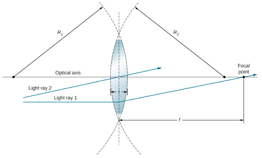
A lens is considered to be thin if its thickness t is much less than the radii of curvature of both surfaces, as shown in Figure 2.5.3. In this case, the rays may be considered to bend once at the center of the lens. For the case drawn in the figure, light ray 1 is parallel to the optical axis, so the outgoing ray is bent once at the center of the lens and goes through the focal point. Another important characteristic of thin lenses is that light rays that pass through the center of the lens are undeviated, as shown by light ray 2.
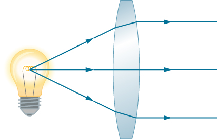
As noted in the initial discussion of Snell’s law, the paths of light rays are exactly reversible. This means that the direction of the arrows could be reversed for all of the rays in Figure 2.5.2. For example, if a point-light source is placed at the focal point of a convex lens, as shown in Figure 2.5.4, parallel light rays emerge from the other side.
Ray Tracing and Thin Lenses
Ray tracing is the technique of determining or following (tracing) the paths taken by light rays. Ray tracing for thin lenses is very similar to the technique we used with spherical mirrors. As for mirrors, ray tracing can accurately describe the operation of a lens. The rules for ray tracing for thin lenses are similar to those of spherical mirrors:
- A ray entering a converging lens parallel to the optical axis passes through the focal point on the other side of the lens (ray 1 in part (a) of Figure 2.5.4). A ray entering a diverging lens parallel to the optical axis exits along the line that passes through the focal point on the same side of the lens (ray 1 in part (b) of the figure).
- A ray passing through the center of either a converging or a diverging lens is not deviated (ray 2 in parts (a) and (b)).
- For a converging lens, a ray that passes through the focal point exits the lens parallel to the optical axis (ray 3 in part (a)). For a diverging lens, a ray that approaches along the line that passes through the focal point on the opposite side exits the lens parallel to the axis (ray 3 in part (b)).

Thin lenses work quite well for monochromatic light (i.e., light of a single wavelength). However, for light that contains several wavelengths (e.g., white light), the lenses work less well. The problem is that, as we learned in the previous chapter, the index of refraction of a material depends on the wavelength of light. This phenomenon is responsible for many colorful effects, such as rainbows. Unfortunately, this phenomenon also leads to aberrations in images formed by lenses. In particular, because the focal distance of the lens depends on the index of refraction, it also depends on the wavelength of the incident light. This means that light of different wavelengths will focus at different points, resulting is so-called “chromatic aberrations.” In particular, the edges of an image of a white object will become colored and blurred. Special lenses called doublets are capable of correcting chromatic aberrations. A doublet is formed by gluing together a converging lens and a diverging lens. The combined doublet lens produces significantly reduced chromatic aberrations.
Image Formation by Thin Lenses
We use ray tracing to investigate different types of images that can be created by a lens. In some circumstances, a lens forms a real image, such as when a movie projector casts an image onto a screen. In other cases, the image is a virtual image, which cannot be projected onto a screen. Where, for example, is the image formed by eyeglasses? We use ray tracing for thin lenses to illustrate how they form images, and then we develop equations to analyze quantitatively the properties of thin lenses.
Consider an object some distance away from a converging lens, as shown in Figure 2.5.6. To find the location and size of the image, we trace the paths of selected light rays originating from one point on the object, in this case, the tip of the arrow. The figure shows three rays from many rays that emanate from the tip of the arrow. These three rays can be traced by using the ray-tracing rules given above.
- Ray 1 enters the lens parallel to the optical axis and passes through the focal point on the opposite side (rule 1).
- Ray 2 passes through the center of the lens and is not deviated (rule 2).
- Ray 3 passes through the focal point on its way to the lens and exits the lens parallel to the optical axis (rule 3).
The three rays cross at a single point on the opposite side of the lens. Thus, the image of the tip of the arrow is located at this point. All rays that come from the tip of the arrow and enter the lens are refracted and cross at the point shown.
After locating the image of the tip of the arrow, we need another point of the image to orient the entire image of the arrow. We chose to locate the image base of the arrow, which is on the optical axis. As explained in the section on spherical mirrors, the base will be on the optical axis just above the image of the tip of the arrow (due to the top-bottom symmetry of the lens). Thus, the image spans the optical axis to the (negative) height shown. Rays from another point on the arrow, such as the middle of the arrow, cross at another common point, thus filling in the rest of the image.
Although three rays are traced in this figure, only two are necessary to locate a point of the image. It is best to trace rays for which there are simple ray-tracing rules.

Several important distances appear in the figure. As for a mirror, we define do to be the object distance, or the distance of an object from the center of a lens. The image distance di is defined to be the distance of the image from the center of a lens. The height of the object and the height of the image are indicated by ho and hi, respectively. Images that appear upright relative to the object have positive heights, and those that are inverted have negative heights. By using the rules of ray tracing and making a scale drawing with paper and pencil, like that in Figure 2.5.6, we can accurately describe the location and size of an image. But the real benefit of ray tracing is in visualizing how images are formed in a variety of situations.
Oblique Parallel Rays and Focal Plane
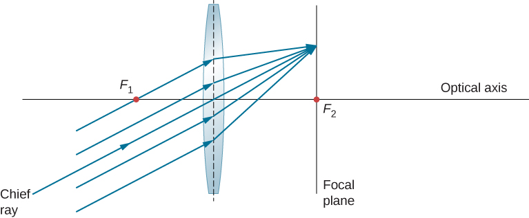
We have seen that rays parallel to the optical axis are directed to the focal point of a converging lens. In the case of a diverging lens, they come out in a direction such that they appear to be coming from the focal point on the opposite side of the lens (i.e., the side from which parallel rays enter the lens). What happens to parallel rays that are not parallel to the optical axis (Figure 2.5.7)? In the case of a converging lens, these rays do not converge at the focal point. Instead, they come together on another point in the plane called the focal plane. The focal plane contains the focal point and is perpendicular to the optical axis. As shown in the figure, parallel rays focus where the ray through the center of the lens crosses the focal plane.
Thin-Lens Equation
Ray tracing allows us to get a qualitative picture of image formation. To obtain numeric information, we derive a pair of equations from a geometric analysis of ray tracing for thin lenses. These equations, called the thin-lens equation and the lens maker’s equation, allow us to quantitatively analyze thin lenses.
Consider the thick bi-convex lens shown in Figure 2.5.8. The index of refraction of the surrounding medium is n1 (if the lens is in air, then n1=1.00) and that of the lens is n2. The radii of curvatures of the two sides are R1 and R2. We wish to find a relation between the object distance do, the image distance di, and the parameters of the lens.

To derive the thin-lens equation, we consider the image formed by the first refracting surface (i.e., left surface) and then use this image as the object for the second refracting surface. In the figure, the image from the first refracting surface is Q′, which is formed by extending backwards the rays from inside the lens (these rays result from refraction at the first surface). This is shown by the dashed lines in the figure. Notice that this image is virtual because no rays actually pass through the point Q′. To find the image distance d′i corresponding to the image Q′, we use Equation 2.4.3. In this case, the object distance is do, the image distance is (d_i\), and the radius of curvature is R1. Inserting these into the relationship derived previous for refraction at curves surfaces gives
n1do+n2d′i=n2−n1R1.
The image is virtual and on the same side as the object, so di′<0 and do>0. The first surface is convex toward the object, so R1>0.
To find the object distance for the object Q formed by refraction from the second interface, note that the role of the indices of refraction n1 and n2 are interchanged in Equation 2.4.3. In Figure 2.5.8, the rays originate in the medium with index n2, whereas in Figure 2.4.3, the rays originate in the medium with index n1. Thus, we must interchange n1 and n2 in Equation 2.4.3. In addition, by consulting again Figure 2.5.8, we see that the object distance is d′o and the image distance is di. The radius of curvature is R2 Inserting these quantities into Equation 2.4.3 gives
n2d′o+n1di=n1−n2R2.
The image is real and on the opposite side from the object, so di>0 and do′>0. The second surface is convex away from the object, so R2<0. Equation ??? can be simplified by noting that
d′o=|d′i|+t,
where we have taken the absolute value because d′i is a negative number, whereas both d′o and t are positive. We can dispense with the absolute value if we negate d′i, which gives
d′o=−d′i+td.
Inserting this into Equation ??? gives
n2−d′i+t+n1di=n1−n2R2.
Summing Equations ??? and ??? gives
n1do+n1di+n2d′i+n2−d′i+t=(n2−n1)(1R1−1R2).
In the thin-lens approximation, we assume that the lens is very thin compared to the first image distance, or t≪d′i (or, equivalently, t≪R1 and t≪R2). In this case, the third and fourth terms on the left-hand side of Equation ??? cancel, leaving us with
n1do+n1di=(n2−n1)(1R1−1R2).
Dividing by n1 gives us finally
1do+1di=(n2n1−1)(1R1−1R2).
The left-hand side looks suspiciously like the mirror equation that we derived above for spherical mirrors. As done for spherical mirrors, we can use ray tracing and geometry to show that, for a thin lens,
where f is the focal length of the thin lens (this derivation is left as an exercise). This is the thin-lens equation. The focal length of a thin lens is the same to the left and to the right of the lens. Combining Equations ??? and ??? gives
1f=(n2n1−1)(1R1−1R2)⏟lens maker’s equation
which is called the lens maker’s equation. It shows that the focal length of a thin lens depends only of the radii of curvature and the index of refraction of the lens and that of the surrounding medium. For a lens in air, n1=1.0 and n2≡n, so the lens maker’s equation reduces to
1f=(n−1)(1R1−1R2).
To properly use the thin-lens equation, the following sign conventions must be obeyed:
- di is positive if the image is on the side opposite the object (i.e., real image); otherwise, di is negative (i.e., virtual image).
- f is positive for a converging lens and negative for a diverging lens.
- R is positive for a surface convex toward the object, and negative for a s urface concave toward object.
Magnification
By using a finite-size object on the optical axis and ray tracing, you can show that the magnification m of an image is
m≡hiho=−dido
(where the three lines mean “is defined as”). This is exactly the same equation as we obtained for mirrors (see Equation 2.3.15). If m>0, then the image has the same vertical orientation as the object (called an “upright” image). If m<0, then the image has the opposite vertical orientation as the object (called an “inverted” image).
Using the Thin-Lens Equation
The thin-lens equation and the lens maker’s equation are broadly applicable to situations involving thin lenses. We explore many features of image formation in the following examples.
Consider a thin converging lens. Where does the image form and what type of image is formed as the object approaches the lens from infinity? This may be seen by using the thin-lens equation for a given focal length to plot the image distance as a function of object distance. In other words, we plot
di=(1f−1do)−1
for a given value of f. For f=1cm, the result is shown in Figure 2.5.9a.

An object much farther than the focal length f from the lens should produce an image near the focal plane, because the second term on the right-hand side of the equation above becomes negligible compared to the first term, so we have di≈f. This can be seen in the plot of part (a) of the figure, which shows that the image distance approaches asymptotically the focal length of 1 cm for larger object distances. As the object approaches the focal plane, the image distance diverges to positive infinity. This is expected because an object at the focal plane produces parallel rays that form an image at infinity (i.e., very far from the lens). When the object is farther than the focal length from the lens, the image distance is positive, so the image is real, on the opposite side of the lens from the object, and inverted (because m=−di/do via Equation ???). When the object is closer than the focal length from the lens, the image distance becomes negative, which means that the image is virtual, on the same side of the lens as the object, and upright.
For a thin diverging lens of focal length f=−1.0cm, a similar plot of image distance vs. object distance is shown in Figure 2.5.10b. In this case, the image distance is negative for all positive object distances, which means that the image is virtual, on the same side of the lens as the object, and upright. These characteristics may also be seen by ray-tracing diagrams (Figure 2.5.10).

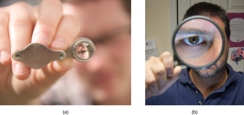
To see a concrete example of upright and inverted images, look at Figure 2.5.11, which shows images formed by converging lenses when the object (the person’s face in this case) is place at different distances from the lens. In part (a) of the figure, the person’s face is farther than one focal length from the lens, so the image is inverted. In part (b), the person’s face is closer than one focal length from the lens, so the image is upright.
Work through the following examples to better understand how thin lenses work.
- Step 1. Determine whether ray tracing, the thin-lens equation, or both would be useful. Even if ray tracing is not used, a careful sketch is always very useful. Write symbols and values on the sketch.
- Step 2. Identify what needs to be determined in the problem (identify the unknowns).
- Step 3. Make a list of what is given or can be inferred from the problem (identify the knowns).
- Step 4. If ray tracing is required, use the ray-tracing rules listed near the beginning of this section.
- Step 5. Most quantitative problems require the use of the thin-lens equation and/or the lens maker’s equation. Solve these for the unknowns and insert the given quantities or use both together to find two unknowns.
- Step 7. Check to see if the answer is reasonable. Are the signs correct? Is the sketch or ray tracing consistent with the calculation?
Example 2.5.1: Using the Lens Maker’s Equation
Find the radius of curvature of a biconcave lens symmetrically ground from a glass with index of refractive 1.55 so that its focal length in air is 20 cm (for a biconcave lens, both surfaces have the same radius of curvature).
Strategy
Use the thin-lens form of the lens maker’s equation:
1f=(n2n1−1)(1R1−1R2)
where R1<0 and R2>0. Since we are making a symmetric biconcave lens, we have |R1|=|R2|.
Solution
We can determine the radius R of curvature from
1f=(n2n1−1)(−2R).
Solving for R and inserting f=−20cm, n2=1.55, and n1=1.00 gives
R=−2f(n2n1−1)=−2(−20cm)(1.551.00−1)=22cm.
Example 2.5.2: Converging Lens and Different Object Distances
Find the location, orientation, and magnification of the image for an 3.0 cm high object at each of the following positions in front of a convex lens of focal length 10.0 cm. (a) do=50.0cm, (b) do=5.00cm, and (c) do=20.0cm.
Strategy
We start with the thin-lens equation (Equation ???)
1di+1do=1f.
Solve this for the image distance di and insert the given object distance and focal length.
Solution
a. For do=50cm and f=+10cm, this gives
di=(1f−1do)−1=(110.0cm−150.0cm)−1=12.5cm
The image is positive, so the image, is real, is on the opposite side of the lens from the object, and is 12.6 cm from the lens. To find the magnification and orientation of the image, use
m=−dido=−12.5cm50.0cm=−0.250.
The negative magnification means that the image is inverted. Since |m|<1, the image is smaller than the object. The size of the image is given by
|hi|=|m|ho=(0.250)(3.0cm)=0.75cm
b. For do=5.00cm and f=+10.0cm
di=(1f−1do)−1=(110.0cm−15.00cm)−1=−10.0cm
The image distance is negative, so the image is virtual, is on the same side of the lens as the object, and is 10 cm from the lens. The magnification and orientation of the image are found from
m=−dido=−−10.0cm5.00cm=+2.00.
The positive magnification means that the image is upright (i.e., it has the same orientation as the object). Since |m|>0, the image is larger than the object. The size of the image is
|hi|=|m|ho=(2.00)(3.0cm)=6.0cm.
c. For do=20cm and f=+10cm
di=(1f−1do)−1=(110.0cm−120.0cm)−1=20.0cm
The image distance is positive, so the image is real, is on the opposite side of the lens from the object, and is 20.0 cm from the lens. The magnification is
m=−dido=−20.0cm20.0cm=−1.00.
The negative magnification means that the image is inverted. Since |m|=1, the image is the same size as the object.
When solving problems in geometric optics, we often need to combine ray tracing and the lens equations. The following example demonstrates this approach.
Example 2.5.3: Choosing the Focal Length and Type of Lens
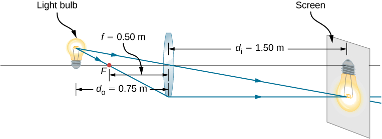
To project an image of a light bulb on a screen 1.50 m away, you need to choose what type of lens to use (converging or diverging) and its focal length (Figure 2.5.12). The distance between the lens and the light bulb is fixed at 0.75 m. Also, what is the magnification and orientation of the image?
Strategy
The image must be real, so you choose to use a converging lens. The focal length can be found by using the thin-lens equation and solving for the focal length. The object distance is do=0.75m and the image distance is di=1.5m.
Solution
Solve the thin lens for the focal length and insert the desired object and image distances:
1do+1di=1ff=(1do+1di)−1=(10.75m+11.5m)−1=0.50m
The magnification is
m=−dido=−1.5m0.75m=−2.0.
Significance
The minus sign for the magnification means that the image is inverted. The focal length is positive, as expected for a converging lens. Ray tracing can be used to check the calculation (Figure 2.5.12). As expected, the image is inverted, is real, and is larger than the object.


