6.3: Photoelectric Effect
- Page ID
- 4521
\( \newcommand{\vecs}[1]{\overset { \scriptstyle \rightharpoonup} {\mathbf{#1}} } \)
\( \newcommand{\vecd}[1]{\overset{-\!-\!\rightharpoonup}{\vphantom{a}\smash {#1}}} \)
\( \newcommand{\id}{\mathrm{id}}\) \( \newcommand{\Span}{\mathrm{span}}\)
( \newcommand{\kernel}{\mathrm{null}\,}\) \( \newcommand{\range}{\mathrm{range}\,}\)
\( \newcommand{\RealPart}{\mathrm{Re}}\) \( \newcommand{\ImaginaryPart}{\mathrm{Im}}\)
\( \newcommand{\Argument}{\mathrm{Arg}}\) \( \newcommand{\norm}[1]{\| #1 \|}\)
\( \newcommand{\inner}[2]{\langle #1, #2 \rangle}\)
\( \newcommand{\Span}{\mathrm{span}}\)
\( \newcommand{\id}{\mathrm{id}}\)
\( \newcommand{\Span}{\mathrm{span}}\)
\( \newcommand{\kernel}{\mathrm{null}\,}\)
\( \newcommand{\range}{\mathrm{range}\,}\)
\( \newcommand{\RealPart}{\mathrm{Re}}\)
\( \newcommand{\ImaginaryPart}{\mathrm{Im}}\)
\( \newcommand{\Argument}{\mathrm{Arg}}\)
\( \newcommand{\norm}[1]{\| #1 \|}\)
\( \newcommand{\inner}[2]{\langle #1, #2 \rangle}\)
\( \newcommand{\Span}{\mathrm{span}}\) \( \newcommand{\AA}{\unicode[.8,0]{x212B}}\)
\( \newcommand{\vectorA}[1]{\vec{#1}} % arrow\)
\( \newcommand{\vectorAt}[1]{\vec{\text{#1}}} % arrow\)
\( \newcommand{\vectorB}[1]{\overset { \scriptstyle \rightharpoonup} {\mathbf{#1}} } \)
\( \newcommand{\vectorC}[1]{\textbf{#1}} \)
\( \newcommand{\vectorD}[1]{\overrightarrow{#1}} \)
\( \newcommand{\vectorDt}[1]{\overrightarrow{\text{#1}}} \)
\( \newcommand{\vectE}[1]{\overset{-\!-\!\rightharpoonup}{\vphantom{a}\smash{\mathbf {#1}}}} \)
\( \newcommand{\vecs}[1]{\overset { \scriptstyle \rightharpoonup} {\mathbf{#1}} } \)
\( \newcommand{\vecd}[1]{\overset{-\!-\!\rightharpoonup}{\vphantom{a}\smash {#1}}} \)
\(\newcommand{\avec}{\mathbf a}\) \(\newcommand{\bvec}{\mathbf b}\) \(\newcommand{\cvec}{\mathbf c}\) \(\newcommand{\dvec}{\mathbf d}\) \(\newcommand{\dtil}{\widetilde{\mathbf d}}\) \(\newcommand{\evec}{\mathbf e}\) \(\newcommand{\fvec}{\mathbf f}\) \(\newcommand{\nvec}{\mathbf n}\) \(\newcommand{\pvec}{\mathbf p}\) \(\newcommand{\qvec}{\mathbf q}\) \(\newcommand{\svec}{\mathbf s}\) \(\newcommand{\tvec}{\mathbf t}\) \(\newcommand{\uvec}{\mathbf u}\) \(\newcommand{\vvec}{\mathbf v}\) \(\newcommand{\wvec}{\mathbf w}\) \(\newcommand{\xvec}{\mathbf x}\) \(\newcommand{\yvec}{\mathbf y}\) \(\newcommand{\zvec}{\mathbf z}\) \(\newcommand{\rvec}{\mathbf r}\) \(\newcommand{\mvec}{\mathbf m}\) \(\newcommand{\zerovec}{\mathbf 0}\) \(\newcommand{\onevec}{\mathbf 1}\) \(\newcommand{\real}{\mathbb R}\) \(\newcommand{\twovec}[2]{\left[\begin{array}{r}#1 \\ #2 \end{array}\right]}\) \(\newcommand{\ctwovec}[2]{\left[\begin{array}{c}#1 \\ #2 \end{array}\right]}\) \(\newcommand{\threevec}[3]{\left[\begin{array}{r}#1 \\ #2 \\ #3 \end{array}\right]}\) \(\newcommand{\cthreevec}[3]{\left[\begin{array}{c}#1 \\ #2 \\ #3 \end{array}\right]}\) \(\newcommand{\fourvec}[4]{\left[\begin{array}{r}#1 \\ #2 \\ #3 \\ #4 \end{array}\right]}\) \(\newcommand{\cfourvec}[4]{\left[\begin{array}{c}#1 \\ #2 \\ #3 \\ #4 \end{array}\right]}\) \(\newcommand{\fivevec}[5]{\left[\begin{array}{r}#1 \\ #2 \\ #3 \\ #4 \\ #5 \\ \end{array}\right]}\) \(\newcommand{\cfivevec}[5]{\left[\begin{array}{c}#1 \\ #2 \\ #3 \\ #4 \\ #5 \\ \end{array}\right]}\) \(\newcommand{\mattwo}[4]{\left[\begin{array}{rr}#1 \amp #2 \\ #3 \amp #4 \\ \end{array}\right]}\) \(\newcommand{\laspan}[1]{\text{Span}\{#1\}}\) \(\newcommand{\bcal}{\cal B}\) \(\newcommand{\ccal}{\cal C}\) \(\newcommand{\scal}{\cal S}\) \(\newcommand{\wcal}{\cal W}\) \(\newcommand{\ecal}{\cal E}\) \(\newcommand{\coords}[2]{\left\{#1\right\}_{#2}}\) \(\newcommand{\gray}[1]{\color{gray}{#1}}\) \(\newcommand{\lgray}[1]{\color{lightgray}{#1}}\) \(\newcommand{\rank}{\operatorname{rank}}\) \(\newcommand{\row}{\text{Row}}\) \(\newcommand{\col}{\text{Col}}\) \(\renewcommand{\row}{\text{Row}}\) \(\newcommand{\nul}{\text{Nul}}\) \(\newcommand{\var}{\text{Var}}\) \(\newcommand{\corr}{\text{corr}}\) \(\newcommand{\len}[1]{\left|#1\right|}\) \(\newcommand{\bbar}{\overline{\bvec}}\) \(\newcommand{\bhat}{\widehat{\bvec}}\) \(\newcommand{\bperp}{\bvec^\perp}\) \(\newcommand{\xhat}{\widehat{\xvec}}\) \(\newcommand{\vhat}{\widehat{\vvec}}\) \(\newcommand{\uhat}{\widehat{\uvec}}\) \(\newcommand{\what}{\widehat{\wvec}}\) \(\newcommand{\Sighat}{\widehat{\Sigma}}\) \(\newcommand{\lt}{<}\) \(\newcommand{\gt}{>}\) \(\newcommand{\amp}{&}\) \(\definecolor{fillinmathshade}{gray}{0.9}\)By the end of this section you will be able to:
- Describe physical characteristics of the photoelectric effect
- Explain why the photoelectric effect cannot be explained by classical physics
- Describe how Einstein’s idea of a particle of radiation explains the photoelectric effect
When a metal surface is exposed to a monochromatic electromagnetic wave of sufficiently short wavelength (or equivalently, above a threshold frequency), the incident radiation is absorbed and the exposed surface emits electrons. This phenomenon is known as the photoelectric effect. Electrons that are emitted in this process are called photoelectrons.
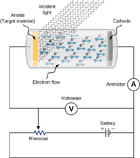
The experimental setup to study the photoelectric effect is shown schematically in Figure \(\PageIndex{1}\). The target material serves as the anode, which becomes the emitter of photoelectrons when it is illuminated by monochromatic radiation. We call this electrode the photoelectrode. Photoelectrons are collected at the cathode, which is kept at a lower potential with respect to the anode. The potential difference between the electrodes can be increased or decreased, or its polarity can be reversed. The electrodes are enclosed in an evacuated glass tube so that photoelectrons do not lose their kinetic energy on collisions with air molecules in the space between electrodes.

When the target material is not exposed to radiation, no current is registered in this circuit because the circuit is broken (note, there is a gap between the electrodes). But when the target material is connected to the negative terminal of a battery and exposed to radiation, a current is registered in this circuit; this current is called the photocurrent. Suppose that we now reverse the potential difference between the electrodes so that the target material now connects with the positive terminal of a battery, and then we slowly increase the voltage. The photocurrent gradually dies out and eventually stops flowing completely at some value of this reversed voltage. The potential difference at which the photocurrent stops flowing is called the stopping potential.
Characteristics of the Photoelectric Effect
The photoelectric effect has three important characteristics that cannot be explained by classical physics: (1) the absence of a lag time, (2) the independence of the kinetic energy of photoelectrons on the intensity of incident radiation, and (3) the presence of a cut-off frequency. Let’s examine each of these characteristics.
The absence of lag time
When radiation strikes the target material in the electrode, electrons are emitted almost instantaneously, even at very low intensities of incident radiation. This absence of lag time contradicts our understanding based on classical physics. Classical physics predicts that for low-energy radiation, it would take significant time before irradiated electrons could gain sufficient energy to leave the electrode surface; however, such an energy buildup is not observed.
The intensity of incident radiation and the kinetic energy of photoelectrons
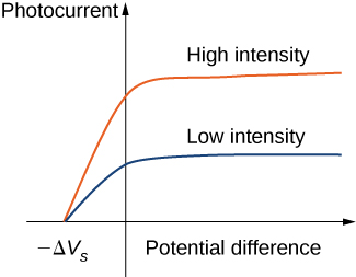
Typical experimental curves are shown in Figure \(\PageIndex{2}\), in which the photocurrent is plotted versus the applied potential difference between the electrodes. For the positive potential difference, the current steadily grows until it reaches a plateau. Furthering the potential increase beyond this point does not increase the photocurrent at all. A higher intensity of radiation produces a higher value of photocurrent. For the negative potential difference, as the absolute value of the potential difference increases, the value of the photocurrent decreases and becomes zero at the stopping potential. For any intensity of incident radiation, whether the intensity is high or low, the value of the stopping potential always stays at one value.
To understand why this result is unusual from the point of view of classical physics, we first have to analyze the energy of photoelectrons. A photoelectron that leaves the surface has kinetic energy \(K\). It gained this energy from the incident electromagnetic wave. In the space between the electrodes, a photoelectron moves in the electric potential and its energy changes by the amount \(q \Delta V\), where \(\Delta V\) is the potential difference and \(q = -e\). Because no forces are present but electric force, by applying the work-energy theorem, we obtain the energy balance \(\Delta K - e\Delta V = 0\) for the photoelectron, where \(\Delta K\) is the change in the photoelectron’s kinetic energy. When the stopping potential \(-\Delta V_s\) is applied, the photoelectron loses its initial kinetic energy \(K_i\) and comes to rest. Thus, its energy balance becomes \((0 - K_i) - e(-\Delta V_s) = 0\), so that \(K_i = e\Delta V_s\). In the presence of the stopping potential, the largest kinetic energy \(K_{max}\) that a photoelectron can have is its initial kinetic energy, which it has at the surface of the photoelectrode. Therefore, the largest kinetic energy of photoelectrons can be directly measured by measuring the stopping potential:
\[K_{max} = e\Delta V_s. \label{PEexpt} \]
At this point we can see where the classical theory is at odds with the experimental results. In classical theory, the photoelectron absorbs electromagnetic energy in a continuous way; this means that when the incident radiation has a high intensity, the kinetic energy in Equation \ref{PEexpt} is expected to be high. Similarly, when the radiation has a low intensity, the kinetic energy is expected to be low. But the experiment shows that the maximum kinetic energy of photoelectrons is independent of the light intensity.

The presence of a cut-off frequency
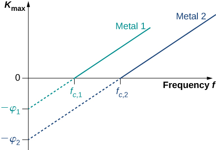
For any metal surface, there is a minimum frequency of incident radiation below which photocurrent does not occur. The value of this cut-off frequency for the photoelectric effect is a physical property of the metal: Different materials have different values of cut-off frequency. Experimental data show a typical linear trend (Figure \(\PageIndex{3}\)). The kinetic energy of photoelectrons at the surface grows linearly with the increasing frequency of incident radiation. Measurements for all metal surfaces give linear plots with one slope. None of these observed phenomena is in accord with the classical understanding of nature. According to the classical description, the kinetic energy of photoelectrons should not depend on the frequency of incident radiation at all, and there should be no cut-off frequency. Instead, in the classical picture, electrons receive energy from the incident electromagnetic wave in a continuous way, and the amount of energy they receive depends only on the intensity of the incident light and nothing else. So in the classical understanding, as long as the light is shining, the photoelectric effect is expected to continue.

The Work Function
The photoelectric effect was explained in 1905 by A. Einstein. Einstein reasoned that if Planck’s hypothesis about energy quanta was correct for describing the energy exchange between electromagnetic radiation and cavity walls, it should also work to describe energy absorption from electromagnetic radiation by the surface of a photoelectrode. He postulated that an electromagnetic wave carries its energy in discrete packets. Einstein’s postulate goes beyond Planck’s hypothesis because it states that the light itself consists of energy quanta. In other words, it states that electromagnetic waves are quantized.
In Einstein’s approach, a beam of monochromatic light of frequency \(f\) is made of photons. A photon is a particle of light. Each photon moves at the speed of light and carries an energy quantum \(E_f\). A photon’s energy depends only on its frequency \(f\). Explicitly, the energy of a photon is
\[E_f = hf \label{planck} \]
where \(h\) is Planck’s constant. In the photoelectric effect, photons arrive at the metal surface and each photon gives away all of its energy to only one electron on the metal surface. This transfer of energy from photon to electron is of the “all or nothing” type, and there are no fractional transfers in which a photon would lose only part of its energy and survive. The essence of a quantum phenomenon is either a photon transfers its entire energy and ceases to exist or there is no transfer at all. This is in contrast with the classical picture, where fractional energy transfers are permitted. Having this quantum understanding, the energy balance for an electron on the surface that receives the energy \(E_f\) from a photon is
\[E_f = K_{max} + \phi \nonumber \]
where \(K_max\) is the kinetic energy, given by Equation \ref{PEexpt}, that an electron has at the very instant it gets detached from the surface. In this energy balance equation, \(\phi\) is the energy needed to detach a photoelectron from the surface. This energy \(\phi\) is called the work function of the metal. Each metal has its characteristic work function, as illustrated in Table \(\PageIndex{1}\). To obtain the kinetic energy of photoelectrons at the surface, we simply invert the energy balance equation and use Equation \ref{planck} to express the energy of the absorbed photon. This gives us the expression for the kinetic energy of photoelectrons, which explicitly depends on the frequency of incident radiation:
\[K_{max}=hf−ϕ \label{PEeffect} \]
Equation \ref{PEeffect} has a simple mathematical form but its physics is profound. We can now elaborate on the physical meaning behind this equation.
| Metal | \(\phi\) (eV) |
|---|---|
| Na | 2.46 |
| Al | 4.08 |
| Pb | 4.14 |
| Zn | 4.31 |
| Fe | 4.50 |
| Cu | 4.70 |
| Ag | 4.73 |
| Pt | 6.35 |
In Einstein’s interpretation, interactions take place between individual electrons and individual photons. The absence of a lag time means that these one-on-one interactions occur instantaneously. This interaction time cannot be increased by lowering the light intensity. The light intensity corresponds to the number of photons arriving at the metal surface per unit time. Even at very low light intensities, the photoelectric effect still occurs because the interaction is between one electron and one photon. As long as there is at least one photon with enough energy to transfer it to a bound electron, a photoelectron will appear on the surface of the photoelectrode.
The existence of the cut-off frequency \(f_c\) for the photoelectric effect follows from Equation \ref{PEeffect} because the kinetic energy \(K_{max}\) of the photoelectron can take only positive values. This means that there must be some threshold frequency for which the kinetic energy is zero, \(0 = hf_c - \phi\). In this way, we obtain the explicit formula for cut-off frequency:
\[f_c = \frac{\phi}{h}. \label{6.15} \]
Cut-off frequency depends only on the work function of the metal and is in direct proportion to it. When the work function is large (when electrons are bound fast to the metal surface), the energy of the threshold photon must be large to produce a photoelectron, and then the corresponding threshold frequency is large. Photons with frequencies larger than the threshold frequency \(f_c\) always produce photoelectrons because they have \(K_{max} > 0\). Photons with frequencies smaller than \(f_c\) do not have enough energy to produce photoelectrons. Therefore, when incident radiation has a frequency below the cut-off frequency, the photoelectric effect is not observed. Because frequency \(f\) and wavelength \(\lambda\) of electromagnetic waves are related by the fundamental relation \(\lambda f = c\) (where cc is the speed of light in vacuum), the cut-off frequency has its corresponding cut-off wavelength \(\lambda_c\):
\[\lambda_c = \frac{c}{f_c} = \frac{c}{\phi /h} = \frac{hc}{\phi}. \label{6.16} \]
In this equation, \(hc = 1240 \, eV \cdot nm\). Our observations can be restated in the following equivalent way: When the incident radiation has wavelengths longer than the cut-off wavelength, the photoelectric effect does not occur.
Radiation with wavelength 300 nm is incident on a silver surface. Will photoelectrons be observed?
Strategy
Photoelectrons can be ejected from the metal surface only when the incident radiation has a shorter wavelength than the cut-off wavelength. The work function of silver is \(\phi = 4.73 \, eV\) (Table \(\PageIndex{1}\)). To make the estimate, we use Equation \ref{6.16}.
Solution
The threshold wavelength for observing the photoelectric effect in silver is
\[\begin{align*} \lambda_c &= \frac{hc}{\phi} \\[4pt] &= \frac{1240 \, eV \cdot nm}{4.73 \, eV} = 262 \, nm. \end{align*} \nonumber \]
The incident radiation has wavelength 300 nm, which is longer than the cut-off wavelength; therefore, photoelectrons are not observed.
Significance
If the photoelectrode were made of sodium instead of silver, the cut-off wavelength would be 504 nm and photoelectrons would be observed.
Equation \ref{PEeffect} in Einstein’s model tells us that the maximum kinetic energy of photoelectrons is a linear function of the frequency of incident radiation, which is illustrated in Figure \(\PageIndex{3}\). For any metal, the slope of this plot has a value of Planck’s constant. The intercept with the \(K_{max}\)-axis gives us a value of the work function that is characteristic for the metal. On the other hand, \(K_{max}\) can be directly measured in the experiment by measuring the value of the stopping potential \(\delta V_s\) (see Equation \ref{PEexpt}) at which the photocurrent stops. These direct measurements allow us to determine experimentally the value of Planck’s constant, as well as work functions of materials.
Einstein’s model also gives a straightforward explanation for the photocurrent values shown in Figure \(\PageIndex{3}\). For example, doubling the intensity of radiation translates to doubling the number of photons that strike the surface per unit time. The larger the number of photons, the larger is the number of photoelectrons, which leads to a larger photocurrent in the circuit. This is how radiation intensity affects the photocurrent. The photocurrent must reach a plateau at some value of potential difference because, in unit time, the number of photoelectrons is equal to the number of incident photons and the number of incident photons does not depend on the applied potential difference at all, but only on the intensity of incident radiation. The stopping potential does not change with the radiation intensity because the kinetic energy of photoelectrons (see Equation \ref{PEeffect}) does not depend on the radiation intensity.
When a 180-nm light is used in an experiment with an unknown metal, the measured photocurrent drops to zero at potential – 0.80 V. Determine the work function of the metal and its cut-off frequency for the photoelectric effect.
Strategy
To find the cut-off frequency \(f_c\), we use Equation \ref{6.15}, but first we must find the work function \(\phi\). To find \(\phi\), we use Equation \ref{PEexpt} and Equation \ref{PEeffect}. Photocurrent drops to zero at the stopping value of potential, so we identify \(\Delta V_s = 0.8 V\).
Solution
We use Equation \ref{PEexpt} to find the kinetic energy of the photoelectrons:
\[K_{max} = e\Delta V_s = e(0.80 V) = 0.80 \, eV. \nonumber \]
Now we solve Equation for \(\phi\):
\[\phi = hf - K_{max} = \frac{hc}{\lambda} - K_{max} = \frac{1240 \, eV \cdot m}{180 \, nm} − 0.80 \, eV = 6.09eV. \nonumber \]
Finally, we use Equation to find the cut-off frequency:
\[f_c = \frac{\phi}{h} \frac{6.09 \, eV}{4.136 \times 10^{-15} eV \cdot s} = 1.47 \times 10^{-15} Hz. \nonumber \]
Significance
In calculations like the one shown in this example, it is convenient to use Planck’s constant in the units of \(eV \cdot s\) and express all energies in eV instead of joules.
A 430-nm violet light is incident on a calcium photoelectrode with a work function of 2.71 eV. Find the energy of the incident photons and the maximum kinetic energy of ejected electrons.
Strategy
The energy of the incident photon is \(E_f = hf = hc/\lambda\),, where we use \(f\lambda = c\). To obtain the maximum energy of the ejected electrons, we use Equation \ref{6.16}.
Solution
\[E_f = \frac{hc}{\lambda} = \frac{1240 \, eV \cdot nm}{430 \, nm} = 2.88 \, eV, \, K_{max} = E_f − \phi = 2.88 \, eV − 2.71 \, eV = 0.17 \, eV \nonumber \]
Significance
In this experimental setup, photoelectrons stop flowing at the stopping potential of 0.17 V.
A yellow 589-nm light is incident on a surface whose work function is 1.20 eV. What is the stopping potential? What is the cut-off wavelength?
- Answer
-
\(-0.91 \, V\) 1040 nm
Cut-off frequency for the photoelectric effect in some materials is \(8.0×10^{13}Hz.\) When the incident light has a frequency of \(1.2×10^{14}Hz\), the stopping potential is measured as – 0.16 V. Estimate a value of Planck’s constant from these data (in units J⋅sJ·s and eV⋅seV·s) and determine the percentage error of your estimation.
- Answer
-
\(h = 6.40 \times 10^{-34} J \cdot s = 4.0 \times 10^{-15} eV \cdot s\); \(-3.5\%\)


