8.2: Capacitors and Capacitance
- Page ID
- 4393
\( \newcommand{\vecs}[1]{\overset { \scriptstyle \rightharpoonup} {\mathbf{#1}} } \)
\( \newcommand{\vecd}[1]{\overset{-\!-\!\rightharpoonup}{\vphantom{a}\smash {#1}}} \)
\( \newcommand{\dsum}{\displaystyle\sum\limits} \)
\( \newcommand{\dint}{\displaystyle\int\limits} \)
\( \newcommand{\dlim}{\displaystyle\lim\limits} \)
\( \newcommand{\id}{\mathrm{id}}\) \( \newcommand{\Span}{\mathrm{span}}\)
( \newcommand{\kernel}{\mathrm{null}\,}\) \( \newcommand{\range}{\mathrm{range}\,}\)
\( \newcommand{\RealPart}{\mathrm{Re}}\) \( \newcommand{\ImaginaryPart}{\mathrm{Im}}\)
\( \newcommand{\Argument}{\mathrm{Arg}}\) \( \newcommand{\norm}[1]{\| #1 \|}\)
\( \newcommand{\inner}[2]{\langle #1, #2 \rangle}\)
\( \newcommand{\Span}{\mathrm{span}}\)
\( \newcommand{\id}{\mathrm{id}}\)
\( \newcommand{\Span}{\mathrm{span}}\)
\( \newcommand{\kernel}{\mathrm{null}\,}\)
\( \newcommand{\range}{\mathrm{range}\,}\)
\( \newcommand{\RealPart}{\mathrm{Re}}\)
\( \newcommand{\ImaginaryPart}{\mathrm{Im}}\)
\( \newcommand{\Argument}{\mathrm{Arg}}\)
\( \newcommand{\norm}[1]{\| #1 \|}\)
\( \newcommand{\inner}[2]{\langle #1, #2 \rangle}\)
\( \newcommand{\Span}{\mathrm{span}}\) \( \newcommand{\AA}{\unicode[.8,0]{x212B}}\)
\( \newcommand{\vectorA}[1]{\vec{#1}} % arrow\)
\( \newcommand{\vectorAt}[1]{\vec{\text{#1}}} % arrow\)
\( \newcommand{\vectorB}[1]{\overset { \scriptstyle \rightharpoonup} {\mathbf{#1}} } \)
\( \newcommand{\vectorC}[1]{\textbf{#1}} \)
\( \newcommand{\vectorD}[1]{\overrightarrow{#1}} \)
\( \newcommand{\vectorDt}[1]{\overrightarrow{\text{#1}}} \)
\( \newcommand{\vectE}[1]{\overset{-\!-\!\rightharpoonup}{\vphantom{a}\smash{\mathbf {#1}}}} \)
\( \newcommand{\vecs}[1]{\overset { \scriptstyle \rightharpoonup} {\mathbf{#1}} } \)
\( \newcommand{\vecd}[1]{\overset{-\!-\!\rightharpoonup}{\vphantom{a}\smash {#1}}} \)
\(\newcommand{\avec}{\mathbf a}\) \(\newcommand{\bvec}{\mathbf b}\) \(\newcommand{\cvec}{\mathbf c}\) \(\newcommand{\dvec}{\mathbf d}\) \(\newcommand{\dtil}{\widetilde{\mathbf d}}\) \(\newcommand{\evec}{\mathbf e}\) \(\newcommand{\fvec}{\mathbf f}\) \(\newcommand{\nvec}{\mathbf n}\) \(\newcommand{\pvec}{\mathbf p}\) \(\newcommand{\qvec}{\mathbf q}\) \(\newcommand{\svec}{\mathbf s}\) \(\newcommand{\tvec}{\mathbf t}\) \(\newcommand{\uvec}{\mathbf u}\) \(\newcommand{\vvec}{\mathbf v}\) \(\newcommand{\wvec}{\mathbf w}\) \(\newcommand{\xvec}{\mathbf x}\) \(\newcommand{\yvec}{\mathbf y}\) \(\newcommand{\zvec}{\mathbf z}\) \(\newcommand{\rvec}{\mathbf r}\) \(\newcommand{\mvec}{\mathbf m}\) \(\newcommand{\zerovec}{\mathbf 0}\) \(\newcommand{\onevec}{\mathbf 1}\) \(\newcommand{\real}{\mathbb R}\) \(\newcommand{\twovec}[2]{\left[\begin{array}{r}#1 \\ #2 \end{array}\right]}\) \(\newcommand{\ctwovec}[2]{\left[\begin{array}{c}#1 \\ #2 \end{array}\right]}\) \(\newcommand{\threevec}[3]{\left[\begin{array}{r}#1 \\ #2 \\ #3 \end{array}\right]}\) \(\newcommand{\cthreevec}[3]{\left[\begin{array}{c}#1 \\ #2 \\ #3 \end{array}\right]}\) \(\newcommand{\fourvec}[4]{\left[\begin{array}{r}#1 \\ #2 \\ #3 \\ #4 \end{array}\right]}\) \(\newcommand{\cfourvec}[4]{\left[\begin{array}{c}#1 \\ #2 \\ #3 \\ #4 \end{array}\right]}\) \(\newcommand{\fivevec}[5]{\left[\begin{array}{r}#1 \\ #2 \\ #3 \\ #4 \\ #5 \\ \end{array}\right]}\) \(\newcommand{\cfivevec}[5]{\left[\begin{array}{c}#1 \\ #2 \\ #3 \\ #4 \\ #5 \\ \end{array}\right]}\) \(\newcommand{\mattwo}[4]{\left[\begin{array}{rr}#1 \amp #2 \\ #3 \amp #4 \\ \end{array}\right]}\) \(\newcommand{\laspan}[1]{\text{Span}\{#1\}}\) \(\newcommand{\bcal}{\cal B}\) \(\newcommand{\ccal}{\cal C}\) \(\newcommand{\scal}{\cal S}\) \(\newcommand{\wcal}{\cal W}\) \(\newcommand{\ecal}{\cal E}\) \(\newcommand{\coords}[2]{\left\{#1\right\}_{#2}}\) \(\newcommand{\gray}[1]{\color{gray}{#1}}\) \(\newcommand{\lgray}[1]{\color{lightgray}{#1}}\) \(\newcommand{\rank}{\operatorname{rank}}\) \(\newcommand{\row}{\text{Row}}\) \(\newcommand{\col}{\text{Col}}\) \(\renewcommand{\row}{\text{Row}}\) \(\newcommand{\nul}{\text{Nul}}\) \(\newcommand{\var}{\text{Var}}\) \(\newcommand{\corr}{\text{corr}}\) \(\newcommand{\len}[1]{\left|#1\right|}\) \(\newcommand{\bbar}{\overline{\bvec}}\) \(\newcommand{\bhat}{\widehat{\bvec}}\) \(\newcommand{\bperp}{\bvec^\perp}\) \(\newcommand{\xhat}{\widehat{\xvec}}\) \(\newcommand{\vhat}{\widehat{\vvec}}\) \(\newcommand{\uhat}{\widehat{\uvec}}\) \(\newcommand{\what}{\widehat{\wvec}}\) \(\newcommand{\Sighat}{\widehat{\Sigma}}\) \(\newcommand{\lt}{<}\) \(\newcommand{\gt}{>}\) \(\newcommand{\amp}{&}\) \(\definecolor{fillinmathshade}{gray}{0.9}\)By the end of this section, you will be able to:
- Explain the concepts of a capacitor and its capacitance
- Describe how to evaluate the capacitance of a system of conductors
A capacitor is a device used to store electrical charge and electrical energy. It consists of at least two electrical conductors separated by a distance. (Note that such electrical conductors are sometimes referred to as “electrodes,” but more correctly, they are “capacitor plates.”) The space between capacitors may simply be a vacuum, and, in that case, a capacitor is then known as a “vacuum capacitor.” However, the space is usually filled with an insulating material known as a dielectric. (You will learn more about dielectrics in the sections on dielectrics later in this chapter.) The amount of storage in a capacitor is determined by a property called capacitance, which you will learn more about a bit later in this section.
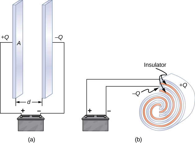
Capacitors have applications ranging from filtering static from radio reception to energy storage in heart defibrillators. Typically, commercial capacitors have two conducting parts close to one another but not touching, such as those in Figure \(\PageIndex{1}\). Most of the time, a dielectric is used between the two plates. When battery terminals are connected to an initially uncharged capacitor, the battery potential moves a small amount of charge of magnitude \(Q\) from the positive plate to the negative plate. The capacitor remains neutral overall, but with charges \(+Q\) and \(-Q\) residing on opposite plates.
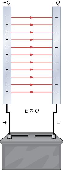
A system composed of two identical parallel-conducting plates separated by a distance is called a parallel-plate capacitor (Figure \(\PageIndex{2}\)). The magnitude of the electrical field in the space between the parallel plates is \(E = \sigma/\epsilon_0\), where \(\sigma\) denotes the surface charge density on one plate (recall that \(\sigma\) is the charge \(Q\) per the surface area \(A\)). Thus, the magnitude of the field is directly proportional to \(Q\).
Capacitors with different physical characteristics (such as shape and size of their plates) store different amounts of charge for the same applied voltage \(V\) across their plates. The capacitance \(C\) of a capacitor is defined as the ratio of the maximum charge \(Q\) that can be stored in a capacitor to the applied voltage \(V\) across its plates. In other words, capacitance is the largest amount of charge per volt that can be stored on the device:
\[C = \frac{Q}{V} \label{eq1} \]
The SI unit of capacitance is the farad (F), named after Michael Faraday (1791–1867). Since capacitance is the charge per unit voltage, one farad is one coulomb per one volt, or
\[1 \, \mathrm{F} = \frac{1 \, \mathrm{C}}{1 \, \mathrm{V}}. \nonumber \]
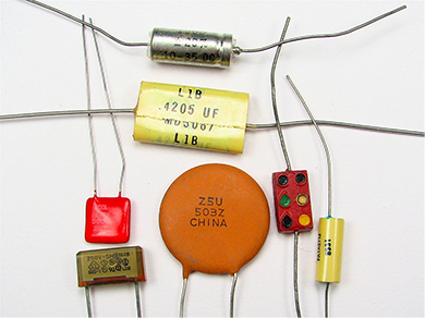
By definition, a 1.0-F capacitor is able to store 1.0 C of charge (a very large amount of charge) when the potential difference between its plates is only 1.0 V. One farad is therefore a very large capacitance. Typical capacitance values range from picofarads (\(1 \, \mathrm{pF} = 10{-12} \mathrm{F}\)) to millifarads \((1 \, \mathrm{mF} = 10^{-3} \mathrm{F})\), which also includes microfarads \((1 \, \mu \mathrm{C} = 10^{-6} \mathrm{F})\). Capacitors can be produced in various shapes and sizes (Figure \(\PageIndex{3}\)).
Calculation of Capacitance
We can calculate the capacitance of a pair of conductors with the standard approach that follows.
- Assume that the capacitor has a charge \(Q\).
- Determine the electrical field \(\vec{E}\) between the conductors. If symmetry is present in the arrangement of conductors, you may be able to use Gauss’s law for this calculation.
- Find the potential difference between the conductors from \[V_B - V_A = - \int_A^B \vec{E} \cdot d\vec{l}, \label{eq0} \] where the path of integration leads from one conductor to the other. The magnitude of the potential difference is then \(V = |V_B - V_A|\).
- With \(V\) known, obtain the capacitance directly from Equation \ref{eq1}.
To show how this procedure works, we now calculate the capacitances of parallel-plate, spherical, and cylindrical capacitors. In all cases, we assume vacuum capacitors (empty capacitors) with no dielectric substance in the space between conductors.
Parallel-Plate Capacitor
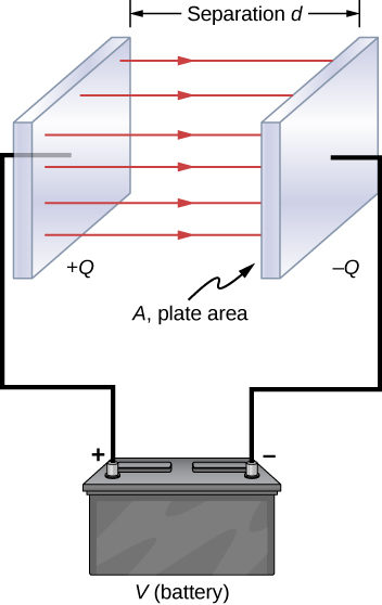
The parallel-plate capacitor (Figure \(\PageIndex{4}\)) has two identical conducting plates, each having a surface area \(A\), separated by a distance \(d\). When a voltage \(V\) is applied to the capacitor, it stores a charge \(Q\), as shown. We can see how its capacitance may depend on \(A\) and \(d\) by considering characteristics of the Coulomb force. We know that force between the charges increases with charge values and decreases with the distance between them. We should expect that the bigger the plates are, the more charge they can store. Thus, \(C\) should be greater for a larger value of \(A\). Similarly, the closer the plates are together, the greater the attraction of the opposite charges on them. Therefore, \(C\) should be greater for a smaller \(d\).
We define the surface charge density \(\sigma\) on the plates as
\[\sigma = \frac{Q}{A}. \nonumber \]
We know from previous chapters that when \(d\) is small, the electrical field between the plates is fairly uniform (ignoring edge effects) and that its magnitude is given by
\[E = \frac{\sigma}{\epsilon_0}, \nonumber \]
where the constant \(\epsilon_0\) is the permittivity of free space, \(\epsilon_0 = 8.85 \times 10^{-12}F/m\). The SI unit of F/m is equivalent to \(C^2/N \cdot m^2\). Since the electrical field \(\vec{E}\) between the plates is uniform, the potential difference between the plates is
\[V = Ed = \frac{\sigma d}{\epsilon_0} = \frac{Qd}{\epsilon_0A}. \nonumber \]
Therefore Equation \ref{eq1} gives the capacitance of a parallel-plate capacitor as
\[C = \frac{Q}{V} = \frac{Q}{Qd/\epsilon_0A} = \epsilon_0\frac{A}{d}. \label{eq2} \]
Notice from this equation that capacitance is a function only of the geometry and what material fills the space between the plates (in this case, vacuum) of this capacitor. In fact, this is true not only for a parallel-plate capacitor, but for all capacitors: The capacitance is independent of \(Q\) or \(V\). If the charge changes, the potential changes correspondingly so that \(Q/V\) remains constant.
- What is the capacitance of an empty parallel-plate capacitor with metal plates that each have an area of \(1.00 \, m^2\), separated by 1.00 mm?
- How much charge is stored in this capacitor if a voltage of \(3.00 \times 10^3 V\) is applied to it?
Strategy
Finding the capacitance \(C\) is a straightforward application of Equation \ref{eq2}. Once we find \(C\), we can find the charge stored by using Equation \ref{eq1}.
Solution
- Entering the given values into Equation \ref{eq2} yields \[C = \epsilon_0\frac{A}{d} = \left(8.85 \times 10^{-12} \frac{F}{m} \right) \frac{1.00 \, m^2}{1.00 \times 10^{-3}m} = 8.85 \times 10^{-9} F = 8.85 \, nF. \nonumber \] This small capacitance value indicates how difficult it is to make a device with a large capacitance.
- Inverting Equation \ref{eq1} and entering the known values into this equation gives \[Q = CV = (8.85 \times 10^{-9}F)(3.00 \times 10^3 V) = 26.6 \, \mu C. \nonumber \]
Significance
This charge is only slightly greater than those found in typical static electricity applications. Since air breaks down (becomes conductive) at an electrical field strength of about 3.0 MV/m, no more charge can be stored on this capacitor by increasing the voltage.
Suppose you wish to construct a parallel-plate capacitor with a capacitance of 1.0 F. What area must you use for each plate if the plates are separated by 1.0 mm?
Solution
Rearranging Equation \ref{eq2}, we obtain
\[A = \frac{Cd}{\epsilon_0} = \frac{(1.0 \, F)(1.0 \times 10^{-3} m)}{8.85 \times 10^{-12} F/m} = 1.1 \times 10^8 \, m^2. \nonumber \]
Each square plate would have to be 10 km across. It used to be a common prank to ask a student to go to the laboratory stockroom and request a 1-F parallel-plate capacitor, until stockroom attendants got tired of the joke.
The capacitance of a parallel-plate capacitor is 2.0 pF. If the area of each plate is \(2.4 \, cm^2\), what is the plate separation?
- Answer
-
\(1.1 \times 10^{-3}m\)
Verify that \(\sigma/V\) and \(\epsilon_0/d\) have the same physical units.
Spherical Capacitor
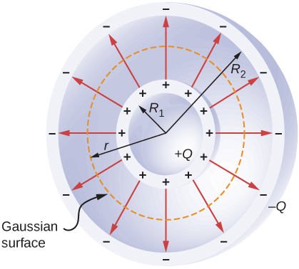
A spherical capacitor is another set of conductors whose capacitance can be easily determined (Figure \(\PageIndex{5}\)). It consists of two concentric conducting spherical shells of radii \(R_1\) (inner shell) and \(R_2\) (outer shell). The shells are given equal and opposite charges \(+Q\) and \(-Q\), respectively. From symmetry, the electrical field between the shells is directed radially outward. We can obtain the magnitude of the field by applying Gauss’s law over a spherical Gaussian surface of radius r concentric with the shells. The enclosed charge is \(+Q\); therefore we have
\[\oint_S \vec{E} \cdot \hat{n}dA = E(4\pi r^2) = \frac{Q}{\epsilon_0}. \nonumber \]
Thus, the electrical field between the conductors is
\[\vec{E} = \frac{1}{4\pi \epsilon_0} \frac{Q}{r^2} \hat{r}. \nonumber \]
We substitute this \(\vec{E}\) into Equation \ref{eq0} and integrate along a radial path between the shells:
\[V = \int_{R_1}^{R_2} \vec{E} \cdot d\vec{l} = \int_{R_1}^{R_2} \left(\frac{1}{4\pi \epsilon_0} \frac{Q}{r^2} \hat{r}\right) \cdot (\hat{r} dr) = \frac{Q}{4\pi \epsilon_0}\int_{R_1}^{R_2} \frac{dr}{r^2} = \frac{Q}{4\pi \epsilon_0}\left(\frac{1}{R_1} - \frac{1}{R_2}\right). \nonumber \]
In this equation, the potential difference between the plates is
\[V = -(V_2 - V_1) = V_1 - V_2. \nonumber \]
We substitute this result into Equation \ref{eq1} to find the capacitance of a spherical capacitor:
\[C = \dfrac{Q}{V} = 4\pi \epsilon_0 \frac{R_1R_2}{R_2 - R_1}. \label{eq3} \]
Calculate the capacitance of a single isolated conducting sphere of radius \(R_1\) and compare it with Equation \ref{eq3} in the limit as \(R_2 \rightarrow \infty\).
Strategy
We assume that the charge on the sphere is \(Q\), and so we follow the four steps outlined earlier. We also assume the other conductor to be a concentric hollow sphere of infinite radius.
Solution
On the outside of an isolated conducting sphere, the electrical field is given by Equation \ref{eq0}. The magnitude of the potential difference between the surface of an isolated sphere and infinity is
\[\begin{align*} V &= \int_{R_1}^{+\infty} \vec{E} \cdot d\vec{l} \\[4pt] &= \frac{Q}{4\pi \epsilon_0} \int_{R_1}^{+\infty} \frac{1}{r^2} \hat{r} \cdot (\hat{r} \, dr) \\[4pt] &= \frac{Q}{4\pi \epsilon_0} \int_{R_1}^{+\infty} \frac{dr}{r^2} \\[4pt] &= \frac{1}{4\pi \epsilon_0} \frac{Q}{R_1} \end{align*} \]
The capacitance of an isolated sphere is therefore
\[C = \frac{Q}{V} = Q\frac{4\pi \epsilon_0 R_1}{Q} = 4\pi \epsilon_0 R_1. \nonumber \]
Significance
The same result can be obtained by taking the limit of Equation \ref{eq3} as \(R_2 \rightarrow \infty\). A single isolated sphere is therefore equivalent to a spherical capacitor whose outer shell has an infinitely large radius.
The radius of the outer sphere of a spherical capacitor is five times the radius of its inner shell. What are the dimensions of this capacitor if its capacitance is 5.00 pF?
- Answer
-
3.59 cm, 17.98 cm
Cylindrical Capacitor
A cylindrical capacitor consists of two concentric, conducting cylinders (Figure \(\PageIndex{6}\)). The inner cylinder, of radius \(R_1\), may either be a shell or be completely solid. The outer cylinder is a shell of inner radius \(R_2\). We assume that the length of each cylinder is l and that the excess charges \(+Q\) and \(-Q\) reside on the inner and outer cylinders, respectively.
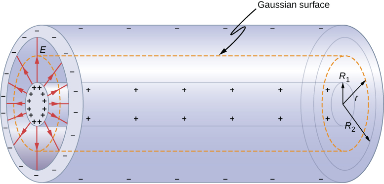
With edge effects ignored, the electrical field between the conductors is directed radially outward from the common axis of the cylinders. Using the Gaussian surface shown in Figure \(\PageIndex{6}\), we have
\[\oint_S \vec{E} \cdot \hat{n} dA = E(2\pi rl) = \frac{Q}{\epsilon_0}. \nonumber \]
Therefore, the electrical field between the cylinders is
\[\vec{E} = \frac{1}{2\pi \epsilon_0} \frac{Q}{r \, l} \hat{r}. \nonumber \]
where \(\hat{r}\) is the unit radial vector along the radius of the cylinder. We can substitute into Equation \ref{eq0} and find the potential difference between the cylinders:
\[V = \int_{R_1}^{R_2} \vec{E} \cdot d\vec{l}_p = \frac{Q}{2\pi \epsilon_0 l} \int_{R_1}^{R_2}\frac{1}{r} \hat{r} \cdot (\hat{r} \, dr) = \frac{Q}{2\pi \epsilon_0 l} \int_{R_1}^{R_2}\frac{dr}{r} = \frac{Q}{2\pi \epsilon_0 l} \ln \, r \bigg|_{R_1}^{R_2} = \frac{Q}{2\pi \epsilon_0 l} \frac{R_2}{R_1}. \nonumber \]
Thus, the capacitance of a cylindrical capacitor is
\[C = \frac{Q}{V} = \frac{2\pi \epsilon_0 \, l}{\ln(R_2/R_1)}. \label{eq10} \]
As in other cases, this capacitance depends only on the geometry of the conductor arrangement. An important application of Equation \ref{eq10} is the determination of the capacitance per unit length of a coaxial cable, which is commonly used to transmit time-varying electrical signals. A coaxial cable consists of two concentric, cylindrical conductors separated by an insulating material. (Here, we assume a vacuum between the conductors, but the physics is qualitatively almost the same when the space between the conductors is filled by a dielectric.) This configuration shields the electrical signal propagating down the inner conductor from stray electrical fields external to the cable. Current flows in opposite directions in the inner and the outer conductors, with the outer conductor usually grounded. Now, from Equation \ref{eq10}, the capacitance per unit length of the coaxial cable is given by
\[\frac{C}{l} = \dfrac{2\pi \epsilon_0}{\ln(R_2/R_1)}. \nonumber \]
In practical applications, it is important to select specific values of \(C/l\). This can be accomplished with appropriate choices of radii of the conductors and of the insulating material between them.
When a cylindrical capacitor is given a charge of 0.500 nC, a potential difference of 20.0 V is measured between the cylinders.
- What is the capacitance of this system?
- If the cylinders are 1.0 m long, what is the ratio of their radii?
- Answer
-
a. 25.0 pF
b. 9.2
Several types of practical capacitors are shown in Figure \(\PageIndex{3}\). Common capacitors are often made of two small pieces of metal foil separated by two small pieces of insulation (Figure \(\PageIndex{1b}\)). The metal foil and insulation are encased in a protective coating, and two metal leads are used for connecting the foils to an external circuit. Some common insulating materials are mica, ceramic, paper, and Teflon™ non-stick coating.
Another popular type of capacitor is an electrolytic capacitor. It consists of an oxidized metal in a conducting paste. The main advantage of an electrolytic capacitor is its high capacitance relative to other common types of capacitors. For example, capacitance of one type of aluminum electrolytic capacitor can be as high as 1.0 F. However, you must be careful when using an electrolytic capacitor in a circuit, because it only functions correctly when the metal foil is at a higher potential than the conducting paste. When reverse polarization occurs, electrolytic action destroys the oxide film. This type of capacitor cannot be connected across an alternating current source, because half of the time, ac voltage would have the wrong polarity, as an alternating current reverses its polarity (see Alternating-Current Circuts on alternating-current circuits).
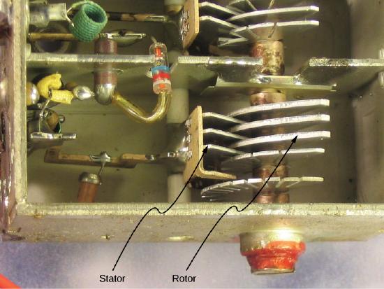
A variable air capacitor (Figure \(\PageIndex{7}\)) has two sets of parallel plates. One set of plates is fixed (indicated as “stator”), and the other set of plates is attached to a shaft that can be rotated (indicated as “rotor”). By turning the shaft, the cross-sectional area in the overlap of the plates can be changed; therefore, the capacitance of this system can be tuned to a desired value. Capacitor tuning has applications in any type of radio transmission and in receiving radio signals from electronic devices. Any time you tune your car radio to your favorite station, think of capacitance.
The symbols shown in Figure \(\PageIndex{8}\) are circuit representations of various types of capacitors. We generally use the symbol shown in Figure \(\PageIndex{8a}\). The symbol in Figure \(\PageIndex{8c}\) represents a variable-capacitance capacitor. Notice the similarity of these symbols to the symmetry of a parallel-plate capacitor. An electrolytic capacitor is represented by the symbol in part Figure \(\PageIndex{8b}\), where the curved plate indicates the negative terminal.

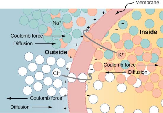
An interesting applied example of a capacitor model comes from cell biology and deals with the electrical potential in the plasma membrane of a living cell (Figure \(\PageIndex{9}\)). Cell membranes separate cells from their surroundings, but allow some selected ions to pass in or out of the cell. The potential difference across a membrane is about 70 mV. The cell membrane may be 7 to 10 nm thick. Treating the cell membrane as a nano-sized capacitor, the estimate of the smallest electrical field strength across its ‘plates’ yields the value
\[E = \frac{V}{d} = \frac{70 \times 10^{-3}V}{10 \times 10^{-9}m} = 7 \times 10^6 V/m > 3 \, MV/m. \nonumber \]
This magnitude of electrical field is great enough to create an electrical spark in the air.
Visit the PhET Explorations: Capacitor Lab to explore how a capacitor works. Change the size of the plates and add a dielectric to see the effect on capacitance. Change the voltage and see charges built up on the plates. Observe the electrical field in the capacitor. Measure the voltage and the electrical field.


