9.5: Statics
- Page ID
- 22257
\( \newcommand{\vecs}[1]{\overset { \scriptstyle \rightharpoonup} {\mathbf{#1}} } \)
\( \newcommand{\vecd}[1]{\overset{-\!-\!\rightharpoonup}{\vphantom{a}\smash {#1}}} \)
\( \newcommand{\id}{\mathrm{id}}\) \( \newcommand{\Span}{\mathrm{span}}\)
( \newcommand{\kernel}{\mathrm{null}\,}\) \( \newcommand{\range}{\mathrm{range}\,}\)
\( \newcommand{\RealPart}{\mathrm{Re}}\) \( \newcommand{\ImaginaryPart}{\mathrm{Im}}\)
\( \newcommand{\Argument}{\mathrm{Arg}}\) \( \newcommand{\norm}[1]{\| #1 \|}\)
\( \newcommand{\inner}[2]{\langle #1, #2 \rangle}\)
\( \newcommand{\Span}{\mathrm{span}}\)
\( \newcommand{\id}{\mathrm{id}}\)
\( \newcommand{\Span}{\mathrm{span}}\)
\( \newcommand{\kernel}{\mathrm{null}\,}\)
\( \newcommand{\range}{\mathrm{range}\,}\)
\( \newcommand{\RealPart}{\mathrm{Re}}\)
\( \newcommand{\ImaginaryPart}{\mathrm{Im}}\)
\( \newcommand{\Argument}{\mathrm{Arg}}\)
\( \newcommand{\norm}[1]{\| #1 \|}\)
\( \newcommand{\inner}[2]{\langle #1, #2 \rangle}\)
\( \newcommand{\Span}{\mathrm{span}}\) \( \newcommand{\AA}{\unicode[.8,0]{x212B}}\)
\( \newcommand{\vectorA}[1]{\vec{#1}} % arrow\)
\( \newcommand{\vectorAt}[1]{\vec{\text{#1}}} % arrow\)
\( \newcommand{\vectorB}[1]{\overset { \scriptstyle \rightharpoonup} {\mathbf{#1}} } \)
\( \newcommand{\vectorC}[1]{\textbf{#1}} \)
\( \newcommand{\vectorD}[1]{\overrightarrow{#1}} \)
\( \newcommand{\vectorDt}[1]{\overrightarrow{\text{#1}}} \)
\( \newcommand{\vectE}[1]{\overset{-\!-\!\rightharpoonup}{\vphantom{a}\smash{\mathbf {#1}}}} \)
\( \newcommand{\vecs}[1]{\overset { \scriptstyle \rightharpoonup} {\mathbf{#1}} } \)
\( \newcommand{\vecd}[1]{\overset{-\!-\!\rightharpoonup}{\vphantom{a}\smash {#1}}} \)
\(\newcommand{\avec}{\mathbf a}\) \(\newcommand{\bvec}{\mathbf b}\) \(\newcommand{\cvec}{\mathbf c}\) \(\newcommand{\dvec}{\mathbf d}\) \(\newcommand{\dtil}{\widetilde{\mathbf d}}\) \(\newcommand{\evec}{\mathbf e}\) \(\newcommand{\fvec}{\mathbf f}\) \(\newcommand{\nvec}{\mathbf n}\) \(\newcommand{\pvec}{\mathbf p}\) \(\newcommand{\qvec}{\mathbf q}\) \(\newcommand{\svec}{\mathbf s}\) \(\newcommand{\tvec}{\mathbf t}\) \(\newcommand{\uvec}{\mathbf u}\) \(\newcommand{\vvec}{\mathbf v}\) \(\newcommand{\wvec}{\mathbf w}\) \(\newcommand{\xvec}{\mathbf x}\) \(\newcommand{\yvec}{\mathbf y}\) \(\newcommand{\zvec}{\mathbf z}\) \(\newcommand{\rvec}{\mathbf r}\) \(\newcommand{\mvec}{\mathbf m}\) \(\newcommand{\zerovec}{\mathbf 0}\) \(\newcommand{\onevec}{\mathbf 1}\) \(\newcommand{\real}{\mathbb R}\) \(\newcommand{\twovec}[2]{\left[\begin{array}{r}#1 \\ #2 \end{array}\right]}\) \(\newcommand{\ctwovec}[2]{\left[\begin{array}{c}#1 \\ #2 \end{array}\right]}\) \(\newcommand{\threevec}[3]{\left[\begin{array}{r}#1 \\ #2 \\ #3 \end{array}\right]}\) \(\newcommand{\cthreevec}[3]{\left[\begin{array}{c}#1 \\ #2 \\ #3 \end{array}\right]}\) \(\newcommand{\fourvec}[4]{\left[\begin{array}{r}#1 \\ #2 \\ #3 \\ #4 \end{array}\right]}\) \(\newcommand{\cfourvec}[4]{\left[\begin{array}{c}#1 \\ #2 \\ #3 \\ #4 \end{array}\right]}\) \(\newcommand{\fivevec}[5]{\left[\begin{array}{r}#1 \\ #2 \\ #3 \\ #4 \\ #5 \\ \end{array}\right]}\) \(\newcommand{\cfivevec}[5]{\left[\begin{array}{c}#1 \\ #2 \\ #3 \\ #4 \\ #5 \\ \end{array}\right]}\) \(\newcommand{\mattwo}[4]{\left[\begin{array}{rr}#1 \amp #2 \\ #3 \amp #4 \\ \end{array}\right]}\) \(\newcommand{\laspan}[1]{\text{Span}\{#1\}}\) \(\newcommand{\bcal}{\cal B}\) \(\newcommand{\ccal}{\cal C}\) \(\newcommand{\scal}{\cal S}\) \(\newcommand{\wcal}{\cal W}\) \(\newcommand{\ecal}{\cal E}\) \(\newcommand{\coords}[2]{\left\{#1\right\}_{#2}}\) \(\newcommand{\gray}[1]{\color{gray}{#1}}\) \(\newcommand{\lgray}[1]{\color{lightgray}{#1}}\) \(\newcommand{\rank}{\operatorname{rank}}\) \(\newcommand{\row}{\text{Row}}\) \(\newcommand{\col}{\text{Col}}\) \(\renewcommand{\row}{\text{Row}}\) \(\newcommand{\nul}{\text{Nul}}\) \(\newcommand{\var}{\text{Var}}\) \(\newcommand{\corr}{\text{corr}}\) \(\newcommand{\len}[1]{\left|#1\right|}\) \(\newcommand{\bbar}{\overline{\bvec}}\) \(\newcommand{\bhat}{\widehat{\bvec}}\) \(\newcommand{\bperp}{\bvec^\perp}\) \(\newcommand{\xhat}{\widehat{\xvec}}\) \(\newcommand{\vhat}{\widehat{\vvec}}\) \(\newcommand{\uhat}{\widehat{\uvec}}\) \(\newcommand{\what}{\widehat{\wvec}}\) \(\newcommand{\Sighat}{\widehat{\Sigma}}\) \(\newcommand{\lt}{<}\) \(\newcommand{\gt}{>}\) \(\newcommand{\amp}{&}\) \(\definecolor{fillinmathshade}{gray}{0.9}\)Statics is the branch of mechanics concerned with the forces and stresses5 needed to keep a system at rest, in a stable equilibrium—so that it will not move, bend or collapse. It is, obviously, extremely important in engineering (particularly in mechanical engineering). In an introductory physics course, we can only deal with it at a very elementary level, by ignoring altogether the deformation of extended objects such as planks and beams (and the associated stresses), and just imposing two simple conditions for static equilibrium: first, the net (external) force on the system must be zero, to make sure its center of mass stays at rest; and second, the net (external) torque on the system must also be zero, so that it does not rotate. These conditions can be symbolically expressed as
\begin{align}
\sum \vec{F}_{e x t}=0 \nonumber \\
\sum \vec{\tau}_{e x t}=0 \label{eq:9.27}
\end{align}
You may ask about which point one should calculate the torques. The answer is that, as long as the first condition is satisfied (sum of the forces is zero), it does not matter! The proof is simple, but you are welcome to skip it if you are not interested.
Suppose you have two points, A and B, around which to calculate the torques. Let \(\vec r_{A1}\), \(\vec r_{A2}\), ... be the position vectors of the points of application of the forces \(\vec F_{1}\), \(\vec F_{2}\)..., relative to point A, and \(\vec r_{B1}\), \(\vec r_{B2}\),..., the same, but relative to point B. If you go all the way back to Figure 1.3.1 (in Chapter 1), you can see that these vectors only differ from the first set by the single constant vector \(\vec r_{AB}\) that gives the position of point B relative to point A: \(\vec{r}_{A 1}=\vec{r}_{A B}+\vec{r}_{B 1}\), etc. Then, for the sum of torques around A we have
\begin{align}
\vec{r}_{A 1} \times \vec{F}_{1}+\vec{r}_{A 2} \times \vec{F}_{2}+\ldots &=\left(\vec{r}_{A B}+\vec{r}_{B 1}\right) \times \vec{F}_{1}+\left(\vec{r}_{A B}+\vec{r}_{A 2}\right) \times \vec{F}_{2}+\ldots \nonumber \\
&=\vec{r}_{A B} \times\left(\vec{F}_{1}+\vec{F}_{2} \ldots\right)+\vec{r}_{B 1} \times \vec{F}_{1}+\vec{r}_{B 2} \times \vec{F}_{2}+\ldots \label{eq:9.28}
\end{align}
The first term on the last line is zero if the sum of all the forces is zero, and what is left is the sum of all the torques around B. This, indeed, for statics pro 1 blems, as long as we are enforcing \(\sum \vec{F}_{e x t}=0\), it does not matter about which point we choose to calculate the torque. A natural choice is the system’s center of mass, since that is typically a point of high symmetry, but we may also choose a point where there are many applied forces, and so get rid of them quickly (since their torques about that point will be zero).
The way all this works is probably best illustrated with an example. Figure \(\PageIndex{1}\) shows a classic one, a ladder leaning against a wall. The sketch on the left shows the angles and dimensions involved, whereas the proper extended free-body diagram, showing all the forces and their points of application, is on the right.
The minimum number of forces needed to balance the system is four: the weight of the ladder (acting at the center of mass), a normal force from the ground, another normal force from the wall, and a force of static friction from the ground that prevents the ladder from slipping. In real life there should also be a force of static friction from the wall, pointing upwards (also to prevent slippage); and, of course, if there is a person on the ladder she will exert an additional force down on it (equal to her weight), applied at whatever point she is standing. I am not going to consider any of these complications, just to keep the example simple, but they could be dealt with in exactly the same way.
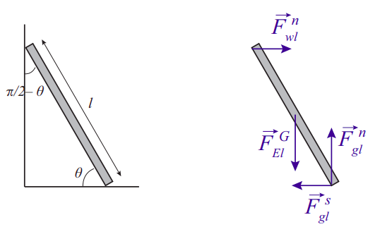
With the convention that a vector quantity without an arrow on top represents that vector’s magnitude, the equation for the balance of the vertical forces reads
\[ F_{g l}^{N}-m g=0 \label{eq:9.29} .\]
For the horizontal forces, we have
\[ F_{w l}^{N}-F_{g l}^{s}=0 \label{eq:9.30} .\]
Then, taking torques around the point where the ladder is in contact with the ground, neither of the two forces applied at that point will contribute, and the condition that the sum of the torques equal zero becomes
\[ F_{w l}^{N} l \sin \theta-m g \frac{l}{2} \cos \theta=0 \label{eq:9.31} .\]
This is because the angle made by the force of gravity with the position vector of its point of application is \(\frac{\pi}{2}-\theta\), and \(\sin \left(\frac{\pi}{2}-\theta\right)=\cos \theta\). From the first equation we get that \(F_{g l}^{N}=m g\); from the second we get that the other normal force, \(F_{w l}^{N}=F_{g l}^{s}\). If we substitute this in (\ref{eq:9.31}), and cancel out \(l\), the length of the ladder, we get the condition
\[ F_{g l}^{s}=\frac{1}{2} m g \cot \theta \label{eq:9.32} .\]
But the force of static friction cannot exceed \(\mu_{s} F_{g l}^{N}=\mu_{s} m g\), so, setting the right-hand side of (\ref{eq:9.32}) to be lower than or equal to \(\mu_s mg\), and canceling the common factor mg, we get the condition
\[ \cot \theta \leq 2 \mu_{s}, \quad \text { or } \quad \tan \theta \geq \frac{1}{2 \mu_{s}} \label{eq:9.33} \]
for the minimum angle \(\theta\) at which we can lean the ladder before it slips and falls.
5A “stress” is a “distributed” force in an extended object, varying continuously from one point to another.