
23.5: Transformers
- Page ID
- 89807

\( \newcommand{\vecs}[1]{\overset { \scriptstyle \rightharpoonup} {\mathbf{#1}} } \)
\( \newcommand{\vecd}[1]{\overset{-\!-\!\rightharpoonup}{\vphantom{a}\smash {#1}}} \)
\( \newcommand{\dsum}{\displaystyle\sum\limits} \)
\( \newcommand{\dint}{\displaystyle\int\limits} \)
\( \newcommand{\dlim}{\displaystyle\lim\limits} \)
\( \newcommand{\id}{\mathrm{id}}\) \( \newcommand{\Span}{\mathrm{span}}\)
( \newcommand{\kernel}{\mathrm{null}\,}\) \( \newcommand{\range}{\mathrm{range}\,}\)
\( \newcommand{\RealPart}{\mathrm{Re}}\) \( \newcommand{\ImaginaryPart}{\mathrm{Im}}\)
\( \newcommand{\Argument}{\mathrm{Arg}}\) \( \newcommand{\norm}[1]{\| #1 \|}\)
\( \newcommand{\inner}[2]{\langle #1, #2 \rangle}\)
\( \newcommand{\Span}{\mathrm{span}}\)
\( \newcommand{\id}{\mathrm{id}}\)
\( \newcommand{\Span}{\mathrm{span}}\)
\( \newcommand{\kernel}{\mathrm{null}\,}\)
\( \newcommand{\range}{\mathrm{range}\,}\)
\( \newcommand{\RealPart}{\mathrm{Re}}\)
\( \newcommand{\ImaginaryPart}{\mathrm{Im}}\)
\( \newcommand{\Argument}{\mathrm{Arg}}\)
\( \newcommand{\norm}[1]{\| #1 \|}\)
\( \newcommand{\inner}[2]{\langle #1, #2 \rangle}\)
\( \newcommand{\Span}{\mathrm{span}}\) \( \newcommand{\AA}{\unicode[.8,0]{x212B}}\)
\( \newcommand{\vectorA}[1]{\vec{#1}} % arrow\)
\( \newcommand{\vectorAt}[1]{\vec{\text{#1}}} % arrow\)
\( \newcommand{\vectorB}[1]{\overset { \scriptstyle \rightharpoonup} {\mathbf{#1}} } \)
\( \newcommand{\vectorC}[1]{\textbf{#1}} \)
\( \newcommand{\vectorD}[1]{\overrightarrow{#1}} \)
\( \newcommand{\vectorDt}[1]{\overrightarrow{\text{#1}}} \)
\( \newcommand{\vectE}[1]{\overset{-\!-\!\rightharpoonup}{\vphantom{a}\smash{\mathbf {#1}}}} \)
\( \newcommand{\vecs}[1]{\overset { \scriptstyle \rightharpoonup} {\mathbf{#1}} } \)
\(\newcommand{\longvect}{\overrightarrow}\)
\( \newcommand{\vecd}[1]{\overset{-\!-\!\rightharpoonup}{\vphantom{a}\smash {#1}}} \)
\(\newcommand{\avec}{\mathbf a}\) \(\newcommand{\bvec}{\mathbf b}\) \(\newcommand{\cvec}{\mathbf c}\) \(\newcommand{\dvec}{\mathbf d}\) \(\newcommand{\dtil}{\widetilde{\mathbf d}}\) \(\newcommand{\evec}{\mathbf e}\) \(\newcommand{\fvec}{\mathbf f}\) \(\newcommand{\nvec}{\mathbf n}\) \(\newcommand{\pvec}{\mathbf p}\) \(\newcommand{\qvec}{\mathbf q}\) \(\newcommand{\svec}{\mathbf s}\) \(\newcommand{\tvec}{\mathbf t}\) \(\newcommand{\uvec}{\mathbf u}\) \(\newcommand{\vvec}{\mathbf v}\) \(\newcommand{\wvec}{\mathbf w}\) \(\newcommand{\xvec}{\mathbf x}\) \(\newcommand{\yvec}{\mathbf y}\) \(\newcommand{\zvec}{\mathbf z}\) \(\newcommand{\rvec}{\mathbf r}\) \(\newcommand{\mvec}{\mathbf m}\) \(\newcommand{\zerovec}{\mathbf 0}\) \(\newcommand{\onevec}{\mathbf 1}\) \(\newcommand{\real}{\mathbb R}\) \(\newcommand{\twovec}[2]{\left[\begin{array}{r}#1 \\ #2 \end{array}\right]}\) \(\newcommand{\ctwovec}[2]{\left[\begin{array}{c}#1 \\ #2 \end{array}\right]}\) \(\newcommand{\threevec}[3]{\left[\begin{array}{r}#1 \\ #2 \\ #3 \end{array}\right]}\) \(\newcommand{\cthreevec}[3]{\left[\begin{array}{c}#1 \\ #2 \\ #3 \end{array}\right]}\) \(\newcommand{\fourvec}[4]{\left[\begin{array}{r}#1 \\ #2 \\ #3 \\ #4 \end{array}\right]}\) \(\newcommand{\cfourvec}[4]{\left[\begin{array}{c}#1 \\ #2 \\ #3 \\ #4 \end{array}\right]}\) \(\newcommand{\fivevec}[5]{\left[\begin{array}{r}#1 \\ #2 \\ #3 \\ #4 \\ #5 \\ \end{array}\right]}\) \(\newcommand{\cfivevec}[5]{\left[\begin{array}{c}#1 \\ #2 \\ #3 \\ #4 \\ #5 \\ \end{array}\right]}\) \(\newcommand{\mattwo}[4]{\left[\begin{array}{rr}#1 \amp #2 \\ #3 \amp #4 \\ \end{array}\right]}\) \(\newcommand{\laspan}[1]{\text{Span}\{#1\}}\) \(\newcommand{\bcal}{\cal B}\) \(\newcommand{\ccal}{\cal C}\) \(\newcommand{\scal}{\cal S}\) \(\newcommand{\wcal}{\cal W}\) \(\newcommand{\ecal}{\cal E}\) \(\newcommand{\coords}[2]{\left\{#1\right\}_{#2}}\) \(\newcommand{\gray}[1]{\color{gray}{#1}}\) \(\newcommand{\lgray}[1]{\color{lightgray}{#1}}\) \(\newcommand{\rank}{\operatorname{rank}}\) \(\newcommand{\row}{\text{Row}}\) \(\newcommand{\col}{\text{Col}}\) \(\renewcommand{\row}{\text{Row}}\) \(\newcommand{\nul}{\text{Nul}}\) \(\newcommand{\var}{\text{Var}}\) \(\newcommand{\corr}{\text{corr}}\) \(\newcommand{\len}[1]{\left|#1\right|}\) \(\newcommand{\bbar}{\overline{\bvec}}\) \(\newcommand{\bhat}{\widehat{\bvec}}\) \(\newcommand{\bperp}{\bvec^\perp}\) \(\newcommand{\xhat}{\widehat{\xvec}}\) \(\newcommand{\vhat}{\widehat{\vvec}}\) \(\newcommand{\uhat}{\widehat{\uvec}}\) \(\newcommand{\what}{\widehat{\wvec}}\) \(\newcommand{\Sighat}{\widehat{\Sigma}}\) \(\newcommand{\lt}{<}\) \(\newcommand{\gt}{>}\) \(\newcommand{\amp}{&}\) \(\definecolor{fillinmathshade}{gray}{0.9}\)The electric power generated in power stations is transmitted using high-voltage transmission lines, typically with voltages above \(300000\text{V}\) for long distances. However, that voltage is not usable in our households, as our appliances expect a voltage around \(120\text{V}\) (or \(\220\text{V}\) in Europe). Transformers use electromagnetic induction to transform one alternating voltage into another. Figure \(\PageIndex{1}\) illustrates a transformer.
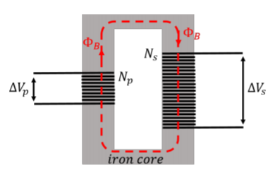
The transformer has two coils, the “primary” and the “secondary”, with different numbers of loops, \(N_p\), and \(N_s\), respectively. The coils are wrapped around an iron core, which can transmit the magnetic flux generated in the primary coil to the secondary coil. In the transformer, an alternating voltage, \(\Delta V_p\), is applied to the primary coil, and transformed into the desired voltage, \(\Delta V_s\), in the secondary coil.
The current in the primary coil creates a magnetic field. Those field lines are transmitted by the iron core into the second coil. A voltage is only induced in the secondary coil if the magnetic flux through the secondary coil changes with time. Thus, transformers only work with alternating voltages, so that the magnetic field created by the primary coil changes continuously. Both coils will have the same magnetic flux, \(\Phi_B\), through them, since they have the same area. The voltage in the primary coil is given by Faraday’s Law:
\[\begin{aligned} \Delta V_p = N_p \frac{d\Phi_B}{dt}\end{aligned}\]
as is the voltage in the secondary coil:
\[\begin{aligned} \Delta V_s = N_s \frac{d\Phi_B}{dt}\end{aligned}\]
Since the flux (and thus its time-derivative) are the same in both coils, we can isolate the time-derivative in each equation to obtain the relationship between the voltages in the two coils:
\[\begin{aligned} \frac{\Delta V_p}{N_p}&=\frac{\Delta V_s}{N_s}\\[4pt] \therefore \Delta V_s &= \frac{N_p}{N_s}\Delta V_p\end{aligned}\]
Thus, with a transformer, one simply needs to set the ratio of the number of loops in each coil in order to transform one voltage into another.
Which coil in Figure \(\PageIndex{1}\) has the highest voltage?
- The one with the most loops.
- The one with the least loops.
- Answer
-
Which coil in Figure \(\PageIndex{1}\) will have the highest current?
- The one with the most loops.
- The one with the least loops.
- Not enough information to tell.
- Answer
-
A power plant produces energy at rate of \(P=150\text{kW}\), and wishes to transmit this power as efficiently as possible to a town. The power lines between the power plant and the town have a resistance of \(R=0.5\Omega\). Compare the amount of power dissipated in the transmission lines depending on whether the power is transmitted through a voltage of \(300000\text{V}\) or \(300\text{V}\).
Solution
We model the transmission of power from the power plant to the town using the circuit shown in Figure \(\PageIndex{2}\).
We do not know the resistance of the town, but we can still calculate the power that is dissipated in the transmission lines that have a total resistance of \(R=0.5\Omega\). The power plant produces power, \(P\), and transmits it through the lines at a potential difference, \(\Delta V\), resulting in a current, \(I\):
\[\begin{aligned} P &= I\Delta V\\[4pt] \therefore I &= \frac{P}{\Delta V}\end{aligned}\]
The current, \(I\), will dissipate power in the lines at a rate of:
\[\begin{aligned} P_{line} = I^2 R = \frac{P^2}{\Delta V^2}R\end{aligned}\]
With the two different voltages, this corresponds to:
\[\begin{aligned} P_{line}&=\frac{P^2}{\Delta V^2}R=\frac{(150\times 10^{3}\text{W})^2}{(300000\text{V})^2}(0.5\Omega)=0.1\text{W}\\[4pt] P_{line}&=\frac{P^2}{\Delta V^2}R=\frac{(150\times 10^{3}\text{W})^2}{(300\text{V})^2}(0.5\Omega)=125000\text{W}\\[4pt]\end{aligned}\]
Thus, when the power is transmitted at low voltage, more than 80% is dissipated in the transmission lines, whereas an insignificant fraction is dissipated when the power is transmitted at high voltage. This is why we need transformers.