
10.7: Transformers
- Page ID
- 107585

\( \newcommand{\vecs}[1]{\overset { \scriptstyle \rightharpoonup} {\mathbf{#1}} } \)
\( \newcommand{\vecd}[1]{\overset{-\!-\!\rightharpoonup}{\vphantom{a}\smash {#1}}} \)
\( \newcommand{\dsum}{\displaystyle\sum\limits} \)
\( \newcommand{\dint}{\displaystyle\int\limits} \)
\( \newcommand{\dlim}{\displaystyle\lim\limits} \)
\( \newcommand{\id}{\mathrm{id}}\) \( \newcommand{\Span}{\mathrm{span}}\)
( \newcommand{\kernel}{\mathrm{null}\,}\) \( \newcommand{\range}{\mathrm{range}\,}\)
\( \newcommand{\RealPart}{\mathrm{Re}}\) \( \newcommand{\ImaginaryPart}{\mathrm{Im}}\)
\( \newcommand{\Argument}{\mathrm{Arg}}\) \( \newcommand{\norm}[1]{\| #1 \|}\)
\( \newcommand{\inner}[2]{\langle #1, #2 \rangle}\)
\( \newcommand{\Span}{\mathrm{span}}\)
\( \newcommand{\id}{\mathrm{id}}\)
\( \newcommand{\Span}{\mathrm{span}}\)
\( \newcommand{\kernel}{\mathrm{null}\,}\)
\( \newcommand{\range}{\mathrm{range}\,}\)
\( \newcommand{\RealPart}{\mathrm{Re}}\)
\( \newcommand{\ImaginaryPart}{\mathrm{Im}}\)
\( \newcommand{\Argument}{\mathrm{Arg}}\)
\( \newcommand{\norm}[1]{\| #1 \|}\)
\( \newcommand{\inner}[2]{\langle #1, #2 \rangle}\)
\( \newcommand{\Span}{\mathrm{span}}\) \( \newcommand{\AA}{\unicode[.8,0]{x212B}}\)
\( \newcommand{\vectorA}[1]{\vec{#1}} % arrow\)
\( \newcommand{\vectorAt}[1]{\vec{\text{#1}}} % arrow\)
\( \newcommand{\vectorB}[1]{\overset { \scriptstyle \rightharpoonup} {\mathbf{#1}} } \)
\( \newcommand{\vectorC}[1]{\textbf{#1}} \)
\( \newcommand{\vectorD}[1]{\overrightarrow{#1}} \)
\( \newcommand{\vectorDt}[1]{\overrightarrow{\text{#1}}} \)
\( \newcommand{\vectE}[1]{\overset{-\!-\!\rightharpoonup}{\vphantom{a}\smash{\mathbf {#1}}}} \)
\( \newcommand{\vecs}[1]{\overset { \scriptstyle \rightharpoonup} {\mathbf{#1}} } \)
\(\newcommand{\longvect}{\overrightarrow}\)
\( \newcommand{\vecd}[1]{\overset{-\!-\!\rightharpoonup}{\vphantom{a}\smash {#1}}} \)
\(\newcommand{\avec}{\mathbf a}\) \(\newcommand{\bvec}{\mathbf b}\) \(\newcommand{\cvec}{\mathbf c}\) \(\newcommand{\dvec}{\mathbf d}\) \(\newcommand{\dtil}{\widetilde{\mathbf d}}\) \(\newcommand{\evec}{\mathbf e}\) \(\newcommand{\fvec}{\mathbf f}\) \(\newcommand{\nvec}{\mathbf n}\) \(\newcommand{\pvec}{\mathbf p}\) \(\newcommand{\qvec}{\mathbf q}\) \(\newcommand{\svec}{\mathbf s}\) \(\newcommand{\tvec}{\mathbf t}\) \(\newcommand{\uvec}{\mathbf u}\) \(\newcommand{\vvec}{\mathbf v}\) \(\newcommand{\wvec}{\mathbf w}\) \(\newcommand{\xvec}{\mathbf x}\) \(\newcommand{\yvec}{\mathbf y}\) \(\newcommand{\zvec}{\mathbf z}\) \(\newcommand{\rvec}{\mathbf r}\) \(\newcommand{\mvec}{\mathbf m}\) \(\newcommand{\zerovec}{\mathbf 0}\) \(\newcommand{\onevec}{\mathbf 1}\) \(\newcommand{\real}{\mathbb R}\) \(\newcommand{\twovec}[2]{\left[\begin{array}{r}#1 \\ #2 \end{array}\right]}\) \(\newcommand{\ctwovec}[2]{\left[\begin{array}{c}#1 \\ #2 \end{array}\right]}\) \(\newcommand{\threevec}[3]{\left[\begin{array}{r}#1 \\ #2 \\ #3 \end{array}\right]}\) \(\newcommand{\cthreevec}[3]{\left[\begin{array}{c}#1 \\ #2 \\ #3 \end{array}\right]}\) \(\newcommand{\fourvec}[4]{\left[\begin{array}{r}#1 \\ #2 \\ #3 \\ #4 \end{array}\right]}\) \(\newcommand{\cfourvec}[4]{\left[\begin{array}{c}#1 \\ #2 \\ #3 \\ #4 \end{array}\right]}\) \(\newcommand{\fivevec}[5]{\left[\begin{array}{r}#1 \\ #2 \\ #3 \\ #4 \\ #5 \\ \end{array}\right]}\) \(\newcommand{\cfivevec}[5]{\left[\begin{array}{c}#1 \\ #2 \\ #3 \\ #4 \\ #5 \\ \end{array}\right]}\) \(\newcommand{\mattwo}[4]{\left[\begin{array}{rr}#1 \amp #2 \\ #3 \amp #4 \\ \end{array}\right]}\) \(\newcommand{\laspan}[1]{\text{Span}\{#1\}}\) \(\newcommand{\bcal}{\cal B}\) \(\newcommand{\ccal}{\cal C}\) \(\newcommand{\scal}{\cal S}\) \(\newcommand{\wcal}{\cal W}\) \(\newcommand{\ecal}{\cal E}\) \(\newcommand{\coords}[2]{\left\{#1\right\}_{#2}}\) \(\newcommand{\gray}[1]{\color{gray}{#1}}\) \(\newcommand{\lgray}[1]{\color{lightgray}{#1}}\) \(\newcommand{\rank}{\operatorname{rank}}\) \(\newcommand{\row}{\text{Row}}\) \(\newcommand{\col}{\text{Col}}\) \(\renewcommand{\row}{\text{Row}}\) \(\newcommand{\nul}{\text{Nul}}\) \(\newcommand{\var}{\text{Var}}\) \(\newcommand{\corr}{\text{corr}}\) \(\newcommand{\len}[1]{\left|#1\right|}\) \(\newcommand{\bbar}{\overline{\bvec}}\) \(\newcommand{\bhat}{\widehat{\bvec}}\) \(\newcommand{\bperp}{\bvec^\perp}\) \(\newcommand{\xhat}{\widehat{\xvec}}\) \(\newcommand{\vhat}{\widehat{\vvec}}\) \(\newcommand{\uhat}{\widehat{\uvec}}\) \(\newcommand{\what}{\widehat{\wvec}}\) \(\newcommand{\Sighat}{\widehat{\Sigma}}\) \(\newcommand{\lt}{<}\) \(\newcommand{\gt}{>}\) \(\newcommand{\amp}{&}\) \(\definecolor{fillinmathshade}{gray}{0.9}\)By the end of the section, you will be able to:
- Explain why power plants transmit electricity at high voltages and low currents and how they do this
- Develop relationships among current, voltage, and the number of windings in step-up and step-down transformers
Although ac electric power is produced at relatively low voltages, it is sent through transmission lines at very high voltages (as high as 500 kV). The same power can be transmitted at different voltages because power is the product \(I_{rms}V_{rms}\). (For simplicity, we ignore the phase factor \(\cos \, \phi\).) A particular power requirement can therefore be met with a low voltage and a high current or with a high voltage and a low current. The advantage of the high-voltage/low-current choice is that it results in lower \(I_{rms}^2R\) ohmic losses in the transmission lines, which can be significant in lines that are many kilometers long (Figure \(\PageIndex{1}\)).
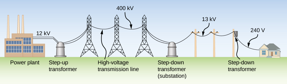
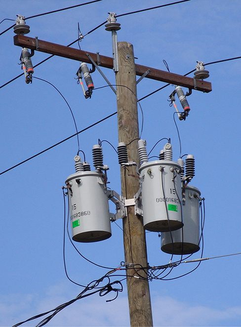
Typically, the alternating emfs produced at power plants are “stepped up” to very high voltages before being transmitted through power lines; then, they must be “stepped down” to relatively safe values (110 or 220 V rms) before they are introduced into homes. The device that transforms voltages from one value to another using induction is the transformer (Figure \(\PageIndex{2}\)).
As Figure \(\PageIndex{3}\) illustrates, a transformer basically consists of two separated coils, or windings, wrapped around a soft iron core. The primary winding has \(N_p\) loops, or turns, and is connected to an alternating voltage \(v_p(t)\). The secondary winding has \(N_s\) turns and is connected to a load resistor \(R_s\). We assume the ideal case for which all magnetic field lines are confined to the core so that the same magnetic flux permeates each turn of both the primary and the secondary windings. We also neglect energy losses to magnetic hysteresis, to ohmic heating in the windings, and to ohmic heating of the induced eddy currents in the core. A good transformer can have losses as low as 1% of the transmitted power, so this is not a bad assumption.
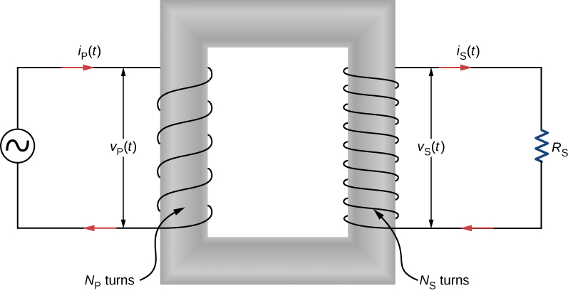
To analyze the transformer circuit, we first consider the primary winding. The input voltage \(v_p(t)\) is equal to the potential difference induced across the primary winding. From Faraday’s law, the induced potential difference is \(- N_p (d\Phi /dt)\), where \(\Phi\) is the flux through one turn of the primary winding. Thus,
\[v_p(t) = -N_p\dfrac{d\Phi}{dt}. \nonumber \]
Similarly, the output voltage \(v_s(t)\) delivered to the load resistor must equal the potential difference induced across the secondary winding. Since the transformer is ideal, the flux through every turn of the secondary winding is also \(\Phi\) and
\[v_s (t) = -N_s \dfrac{d\Phi}{dt}. \nonumber \]
Combining the last two equations, we have
\[v_s(t) = \dfrac{N_s}{N_p} v_p(t). \label{15.20} \]
Hence, with appropriate values for \(N_s\) and \(N_p\), the input voltage \(v_p(t)\) may be “stepped up” \((N_s > N_p)\) or “stepped down” \((N_s < N_p)\) to \(v_s(t)\), the output voltage. This is often abbreviated as the transformer equation,
\[\dfrac{V_s}{V_p} = \dfrac{N_s}{N_p},\label{transformerEQ} \]
which shows that the ratio of the secondary to primary voltages in a transformer equals the ratio of the number of turns in their windings. For a step-up transformer, which increases voltage and decreases current, this ratio is greater than one; for a step-down transformer, which decreases voltage and increases current, this ratio is less than one.
From the law of energy conservation, the power introduced at any instant by \(v_p(t)\) to the primary winding must be equal to the power dissipated in the resistor of the secondary circuit; thus,
\[i_p(t)v_p(t) = i_s(t)v_s(t). \nonumber \]
When combined with Equation \ref{transformerEQ}, this gives
\[i_s(t) = \dfrac{N_p}{N_s} i_p(t). \label{15.22} \]
If the voltage is stepped up, the current is stepped down, and vice versa.
Finally, we can use \(i_s(t) = v_s(t)/R_s\), along with Equation \ref{15.20} and Equation \ref{15.22}, to obtain
\[v_p(t) = i_p \left[\left(\dfrac{N_p}{N_s}\right)^2 R_s\right], \nonumber \]
which tells us that the input voltage \(v_p(t)\) “sees” not a resistance \(R_s\) but rather a resistance
\[R_p = \left(\dfrac{N_p}{N_s}\right)^2 R_s. \nonumber \]
Our analysis has been based on instantaneous values of voltage and current. However, the resulting equations are not limited to instantaneous values; they hold also for maximum and rms values.
A transformer on a utility pole steps the rms voltage down from 12 kV to 240 V.
- What is the ratio of the number of secondary turns to the number of primary turns?
- If the input current to the transformer is 2.0 A, what is the output current?
- Determine the power loss in the transmission line if the total resistance of the transmission line is \(200 \, \Omega\).
- What would the power loss have been if the transmission line was at 240 V the entire length of the line, rather than providing voltage at 12 kV? What does this say about transmission lines?
Strategy
The number of turns related to the voltages is found from Equation \ref{15.20}. The output current is calculated using Equation \ref{15.22}.
Solution
a. Using Equation \ref{15.20} with rms values \(V_p\) and \(V_s\) we have \[\dfrac{N_s}{N_p} = \dfrac{240 \, V}{12 \times 10^3 V} = \dfrac{1}{50}, \nonumber \] so the primary winding has 50 times the number of turns in the secondary winding.
b. From Equation \ref{15.22}, the output rms current \(I_s\) is found using the transformer equation with current
\[I_S = \dfrac{N_p}{N_S} I_p \label{15.23} \]
such that
\[I_s = \dfrac{N_p}{N_s}I_p = (50)(2.0 \, A) = 100 \, A. \nonumber \]
c. The power loss in the transmission line is calculated to be
\[P_{loss} = I_p^2R = (2.0 \, A)^2 (200 \, \Omega) = 800 \, W. \nonumber \]
d. If there were no transformer, the power would have to be sent at 240 V to work for these houses, and the power loss would be
\[P_{loss} = I_s^2R = (100 \, A)^2(200 \, \Omega) = 2 \times 10^6 \, W. \nonumber \]
Therefore, when power needs to be transmitted, we want to avoid power loss. Thus, lines are sent with high voltages and low currents and adjusted with a transformer before power is sent into homes.
Significance
This application of a step-down transformer allows a home that uses 240-V outlets to have 100 A available to draw upon. This can power many devices in the home.
A transformer steps the line voltage down from 110 to 9.0 V so that a current of 0.50 A can be delivered to a doorbell.
- What is the ratio of the number of turns in the primary and secondary windings?
- What is the current in the primary winding?
- What is the resistance seen by the 110-V source?
- Answer a
-
12:1
- Answer b
-
0.042 A
- Answer c
-
\(2.6 \times 10^3 \, \Omega\)