10.6: Single-Slit Diffraction
- Page ID
- 76684
\( \newcommand{\vecs}[1]{\overset { \scriptstyle \rightharpoonup} {\mathbf{#1}} } \)
\( \newcommand{\vecd}[1]{\overset{-\!-\!\rightharpoonup}{\vphantom{a}\smash {#1}}} \)
\( \newcommand{\dsum}{\displaystyle\sum\limits} \)
\( \newcommand{\dint}{\displaystyle\int\limits} \)
\( \newcommand{\dlim}{\displaystyle\lim\limits} \)
\( \newcommand{\id}{\mathrm{id}}\) \( \newcommand{\Span}{\mathrm{span}}\)
( \newcommand{\kernel}{\mathrm{null}\,}\) \( \newcommand{\range}{\mathrm{range}\,}\)
\( \newcommand{\RealPart}{\mathrm{Re}}\) \( \newcommand{\ImaginaryPart}{\mathrm{Im}}\)
\( \newcommand{\Argument}{\mathrm{Arg}}\) \( \newcommand{\norm}[1]{\| #1 \|}\)
\( \newcommand{\inner}[2]{\langle #1, #2 \rangle}\)
\( \newcommand{\Span}{\mathrm{span}}\)
\( \newcommand{\id}{\mathrm{id}}\)
\( \newcommand{\Span}{\mathrm{span}}\)
\( \newcommand{\kernel}{\mathrm{null}\,}\)
\( \newcommand{\range}{\mathrm{range}\,}\)
\( \newcommand{\RealPart}{\mathrm{Re}}\)
\( \newcommand{\ImaginaryPart}{\mathrm{Im}}\)
\( \newcommand{\Argument}{\mathrm{Arg}}\)
\( \newcommand{\norm}[1]{\| #1 \|}\)
\( \newcommand{\inner}[2]{\langle #1, #2 \rangle}\)
\( \newcommand{\Span}{\mathrm{span}}\) \( \newcommand{\AA}{\unicode[.8,0]{x212B}}\)
\( \newcommand{\vectorA}[1]{\vec{#1}} % arrow\)
\( \newcommand{\vectorAt}[1]{\vec{\text{#1}}} % arrow\)
\( \newcommand{\vectorB}[1]{\overset { \scriptstyle \rightharpoonup} {\mathbf{#1}} } \)
\( \newcommand{\vectorC}[1]{\textbf{#1}} \)
\( \newcommand{\vectorD}[1]{\overrightarrow{#1}} \)
\( \newcommand{\vectorDt}[1]{\overrightarrow{\text{#1}}} \)
\( \newcommand{\vectE}[1]{\overset{-\!-\!\rightharpoonup}{\vphantom{a}\smash{\mathbf {#1}}}} \)
\( \newcommand{\vecs}[1]{\overset { \scriptstyle \rightharpoonup} {\mathbf{#1}} } \)
\(\newcommand{\longvect}{\overrightarrow}\)
\( \newcommand{\vecd}[1]{\overset{-\!-\!\rightharpoonup}{\vphantom{a}\smash {#1}}} \)
\(\newcommand{\avec}{\mathbf a}\) \(\newcommand{\bvec}{\mathbf b}\) \(\newcommand{\cvec}{\mathbf c}\) \(\newcommand{\dvec}{\mathbf d}\) \(\newcommand{\dtil}{\widetilde{\mathbf d}}\) \(\newcommand{\evec}{\mathbf e}\) \(\newcommand{\fvec}{\mathbf f}\) \(\newcommand{\nvec}{\mathbf n}\) \(\newcommand{\pvec}{\mathbf p}\) \(\newcommand{\qvec}{\mathbf q}\) \(\newcommand{\svec}{\mathbf s}\) \(\newcommand{\tvec}{\mathbf t}\) \(\newcommand{\uvec}{\mathbf u}\) \(\newcommand{\vvec}{\mathbf v}\) \(\newcommand{\wvec}{\mathbf w}\) \(\newcommand{\xvec}{\mathbf x}\) \(\newcommand{\yvec}{\mathbf y}\) \(\newcommand{\zvec}{\mathbf z}\) \(\newcommand{\rvec}{\mathbf r}\) \(\newcommand{\mvec}{\mathbf m}\) \(\newcommand{\zerovec}{\mathbf 0}\) \(\newcommand{\onevec}{\mathbf 1}\) \(\newcommand{\real}{\mathbb R}\) \(\newcommand{\twovec}[2]{\left[\begin{array}{r}#1 \\ #2 \end{array}\right]}\) \(\newcommand{\ctwovec}[2]{\left[\begin{array}{c}#1 \\ #2 \end{array}\right]}\) \(\newcommand{\threevec}[3]{\left[\begin{array}{r}#1 \\ #2 \\ #3 \end{array}\right]}\) \(\newcommand{\cthreevec}[3]{\left[\begin{array}{c}#1 \\ #2 \\ #3 \end{array}\right]}\) \(\newcommand{\fourvec}[4]{\left[\begin{array}{r}#1 \\ #2 \\ #3 \\ #4 \end{array}\right]}\) \(\newcommand{\cfourvec}[4]{\left[\begin{array}{c}#1 \\ #2 \\ #3 \\ #4 \end{array}\right]}\) \(\newcommand{\fivevec}[5]{\left[\begin{array}{r}#1 \\ #2 \\ #3 \\ #4 \\ #5 \\ \end{array}\right]}\) \(\newcommand{\cfivevec}[5]{\left[\begin{array}{c}#1 \\ #2 \\ #3 \\ #4 \\ #5 \\ \end{array}\right]}\) \(\newcommand{\mattwo}[4]{\left[\begin{array}{rr}#1 \amp #2 \\ #3 \amp #4 \\ \end{array}\right]}\) \(\newcommand{\laspan}[1]{\text{Span}\{#1\}}\) \(\newcommand{\bcal}{\cal B}\) \(\newcommand{\ccal}{\cal C}\) \(\newcommand{\scal}{\cal S}\) \(\newcommand{\wcal}{\cal W}\) \(\newcommand{\ecal}{\cal E}\) \(\newcommand{\coords}[2]{\left\{#1\right\}_{#2}}\) \(\newcommand{\gray}[1]{\color{gray}{#1}}\) \(\newcommand{\lgray}[1]{\color{lightgray}{#1}}\) \(\newcommand{\rank}{\operatorname{rank}}\) \(\newcommand{\row}{\text{Row}}\) \(\newcommand{\col}{\text{Col}}\) \(\renewcommand{\row}{\text{Row}}\) \(\newcommand{\nul}{\text{Nul}}\) \(\newcommand{\var}{\text{Var}}\) \(\newcommand{\corr}{\text{corr}}\) \(\newcommand{\len}[1]{\left|#1\right|}\) \(\newcommand{\bbar}{\overline{\bvec}}\) \(\newcommand{\bhat}{\widehat{\bvec}}\) \(\newcommand{\bperp}{\bvec^\perp}\) \(\newcommand{\xhat}{\widehat{\xvec}}\) \(\newcommand{\vhat}{\widehat{\vvec}}\) \(\newcommand{\uhat}{\widehat{\uvec}}\) \(\newcommand{\what}{\widehat{\wvec}}\) \(\newcommand{\Sighat}{\widehat{\Sigma}}\) \(\newcommand{\lt}{<}\) \(\newcommand{\gt}{>}\) \(\newcommand{\amp}{&}\) \(\definecolor{fillinmathshade}{gray}{0.9}\)By the end of this section, you will be able to:
- Explain the phenomenon of diffraction and the conditions under which it is observed
- Describe diffraction through a single slit
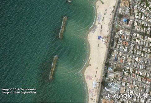
After passing through a narrow aperture (opening), a wave propagating in a specific direction tends to spread out. For example, sound waves that enter a room through an open door can be heard even if the listener is in a part of the room where the geometry of ray propagation dictates that there should only be silence. Similarly, ocean waves passing through an opening in a breakwater can spread throughout the bay inside. (Figure \(\PageIndex{1}\)). The spreading and bending of sound and ocean waves are two examples of diffraction, which is the bending of a wave around the edges of an opening or an obstacle—a phenomenon exhibited by all types of waves.
The diffraction of sound waves is apparent to us because wavelengths in the audible region are approximately the same size as the objects they encounter, a condition that must be satisfied if diffraction effects are to be observed easily. Since the wavelengths of visible light range from approximately 390 to 770 nm, most objects do not diffract light significantly. However, situations do occur in which apertures are small enough that the diffraction of light is observable. For example, if you place your middle and index fingers close together and look through the opening at a light bulb, you can see a rather clear diffraction pattern, consisting of light and dark lines running parallel to your fingers.
Diffraction through a Single Slit
Light passing through a single slit forms a diffraction pattern somewhat different from those formed by double slits or diffraction gratings, which we discussed in the chapter on interference. Figure \(\PageIndex{2}\) shows a single-slit diffraction pattern. Note that the central maximum is larger than maxima on either side and that the intensity decreases rapidly on either side. In contrast, a diffraction grating produces evenly spaced lines that dim slowly on either side of the center.
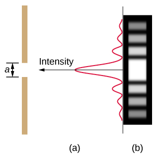
The analysis of single-slit diffraction is illustrated in Figure \(\PageIndex{2}\). Here, the light arrives at the slit, illuminating it uniformly and is in phase across its width. We then consider light propagating onwards from different parts of the same slit. According to Huygens’s principle, every part of the wave front in the slit emits wavelets, as we discussed in The Nature of Light. These are like rays that start out in phase and head in all directions. (Each ray is perpendicular to the wave front of a wavelet.) Assuming the screen is very far away compared with the size of the slit, rays heading toward a common destination are nearly parallel. When they travel straight ahead, as in part (a) of the figure, they remain in phase, and we observe a central maximum. However, when rays travel at an angle θ relative to the original direction of the beam, each ray travels a different distance to a common location, and they can arrive in or out of phase. In part (b), the ray from the bottom travels a distance of one wavelength λ farther than the ray from the top. Thus, a ray from the center travels a distance λ/2 less than the one at the bottom edge of the slit, arrives out of phase, and interferes destructively. A ray from slightly above the center and one from slightly above the bottom also cancel one another. In fact, each ray from the slit interferes destructively with another ray. In other words, a pair-wise cancellation of all rays results in a dark minimum in intensity at this angle. By symmetry, another minimum occurs at the same angle to the right of the incident direction (toward the bottom of the figure) of the light.
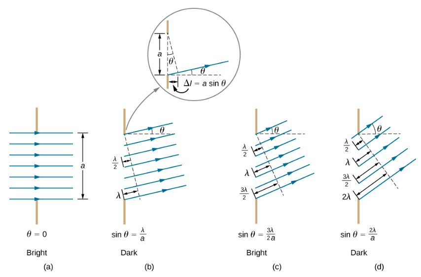
At the larger angle shown in part (c), the path lengths differ by \(3λ/2\) for rays from the top and bottom of the slit. One ray travels a distance \(λ\) different from the ray from the bottom and arrives in phase, interfering constructively. Two rays, each from slightly above those two, also add constructively. Most rays from the slit have another ray to interfere with constructively, and a maximum in intensity occurs at this angle. However, not all rays interfere constructively for this situation, so the maximum is not as intense as the central maximum. Finally, in part (d), the angle shown is large enough to produce a second minimum. As seen in the figure, the difference in path length for rays from either side of the slit is \(a \sin \theta\), and we see that a destructive minimum is obtained when this distance is an integral multiple of the wavelength.
Thus, to obtain destructive interference for a single slit,
\[\underbrace{a \sin θ = mλ}_{\text{destructive interference}} \nonumber \]
where
- \(m = ±1, ±2, ±3,...\),
- \(a\) is the slit width,
- \(λ\) is the light’s wavelength,
- \(θ\) is the angle relative to the original direction of the light, and
- \(m\) is the order of the minimum.
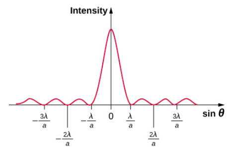
Figure \(\PageIndex{3}\) shows a graph of intensity for single-slit interference, and it is apparent that the maxima on either side of the central maximum are much less intense and not as wide. This effect is explored in Double-Slit Diffraction.
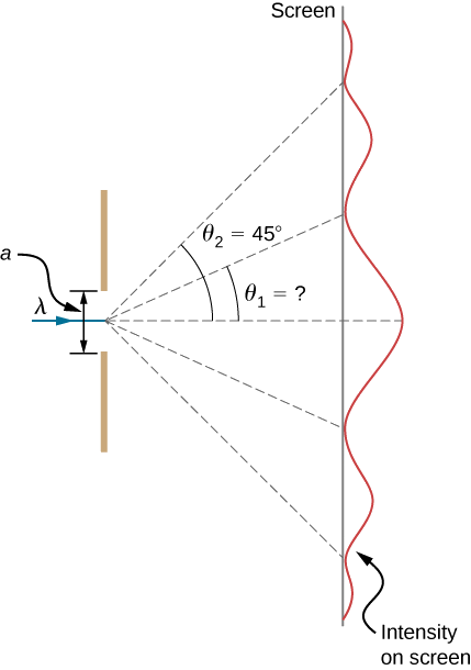
Visible light of wavelength 550 nm falls on a single slit and produces its second diffraction minimum at an angle of 45.0° relative to the incident direction of the light, as in Figure \(\PageIndex{5}\).
- What is the width of the slit?
- At what angle is the first minimum produced?
Strategy
From the given information, and assuming the screen is far away from the slit, we can use the equation \(a \sin θ = mλ\) first to find \(a\), and again to find the angle for the first minimum \(\theta_1\).
Solution
- We are given that \(λ=550\,nm\), \(m=2\), and \(\theta_2 = 45.0°\). Solving the equation \(a \, \sin \, \theta = m\lambda\) for \(a\) and substituting known values gives
\[a = \frac{m\lambda}{\sin \, \theta_2} = \frac{2(550 \, nm)}{\sin \, 45.0°} = \frac{1100 \times 10^{-9} m}{0.707} = 1.56 \times 10^{-6} m. \nonumber \]
- Solving the equation \(a \, \sin \, \theta = m\lambda\) for \(\sin \, \theta_1\) and substituting the known values gives
\[\sin \, \theta_1 = \frac{m\lambda}{a} = \frac{1(550 \times 10^{-9}m)}{1.56 \times 10^{-6}m}. \nonumber \]
Thus the angle \(\theta_1\) is\[\theta_1 = \sin^{-1}0.354 = 20.7°. \nonumber \]
Significance
We see that the slit is narrow (it is only a few times greater than the wavelength of light). This is consistent with the fact that light must interact with an object comparable in size to its wavelength in order to exhibit significant wave effects such as this single-slit diffraction pattern. We also see that the central maximum extends 20.7° on either side of the original beam, for a width of about 41°. The angle between the first and second minima is only about 24°(45.0°−20.7°). Thus, the second maximum is only about half as wide as the central maximum.
Suppose the slit width in Example \(\PageIndex{1}\) is increased to \(1.8 \times 10^{-6} m\). What are the new angular positions for the first, second, and third minima? Would a fourth minimum exist?
- Answer
-
\(17.8^o\), \(37.7^o\), \(66.4^o\); no
By the end of this section, you will be able to:
- Calculate the intensity relative to the central maximum of the single-slit diffraction peaks
- Calculate the intensity relative to the central maximum of an arbitrary point on the screen
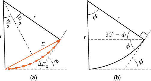
To calculate the intensity of the diffraction pattern, we follow the phasor method used for calculations with ac circuits in Alternating-Current Circuits. If we consider that there are \(N\) Huygens sources across the slit shown previously, with each source separated by a distance a/N from its adjacent neighbors, the path difference between waves from adjacent sources reaching the arbitrary point \(P\) on the screen is \((a/N) \, \sin \theta\). This distance is equivalent to a phase difference of \((2\pi a/\lambda N) \, \sin \, \theta\). The phasor diagram for the waves arriving at the point whose angular position is \(\theta\) is shown in Figure \(\PageIndex{1}\). The amplitude of the phasor for each Huygens wavelet is \(\Delta E_0\), the amplitude of the resultant phasor is \(E\), and the phase difference between the wavelets from the first and the last sources is
\[\phi = \left(\dfrac{2\pi}{\lambda}\right) \, a \, \sin \theta. \nonumber \]
With \(N → ∞\), the phasor diagram approaches a circular arc of length \(N \Delta E_0\) and radius \(r\). Since the length of the arc is \(N \Delta E_0\) for any \(ϕ\), the radius \(r\) of the arc must decrease as \(ϕ\) increases (or equivalently, as the phasors form tighter spirals).
The phasor diagram for ϕ = 0 (the center of the diffraction pattern) is shown in Figure \(\PageIndex{1a}\) using N=30. In this case, the phasors are laid end to end in a straight line of length \(N \Delta E_0\), the radius r goes to infinity, and the resultant has its maximum value \(E = N\Delta E_0\). The intensity of the light can be obtained using the relation \(I = \dfrac{1}{2} c \epsilon_0 E^2\) from Electromagnetic Waves. The intensity of the maximum is then
\[I_0 = \dfrac{1}{2} c\epsilon_0 (N \Delta E_0)^2 = \dfrac{1}{2\mu_0 c}(N\Delta E_0)^2, \nonumber \]
where \(\epsilon_0 = 1/\mu_0 c^2\). The phasor diagrams for the first two zeros of the diffraction pattern are shown in Figure \(\PageIndex{1b}\) and Figure \(\PageIndex{1d}\). In both cases, the phasors add to zero, after rotating through \(\phi = 2\pi\) rad for m = 1 and \(4 \pi\) rad for m = 2.
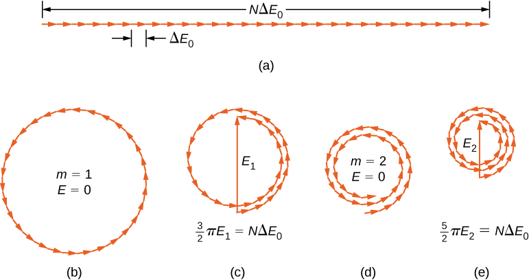
The next two maxima beyond the central maxima are represented by the phasor diagrams of parts (c) and (e). In part (c), the phasors have rotated through \(\phi = 3\pi\) rad and have formed a resultant phasor of magnitude \(E_1\). The length of the arc formed by the phasors is \(N\Delta E_0\). Since this corresponds to 1.5 rotations around a circle of diameter \(E_1\), we have
\[\dfrac{3}{2} \pi E_1 = N \Delta E_0, \nonumber \]
so
\[E_1 = \dfrac{2N\Delta E_0}{3\pi} \nonumber \]
and
\[I_1 = \dfrac{1}{2\mu_0 c}E_1^2 = \dfrac{4(N\Delta E_0)^2}{(9\pi^2)(2\mu_0c)} = 0.045 I_0, \nonumber \]
where
\[I_0 = \dfrac{(N\Delta E_0)^2}{2\mu_0 c}. \nonumber \]
In part (e), the phasors have rotated through \(\phi = 5\pi\) rad, corresponding to 2.5 rotations around a circle of diameter \(E_2\) and arc length \(N\Delta E_0\). This results in \(I_2 = 0.016 I_0\). The proof is left as an exercise for the student (Exercise 4.119).
These two maxima actually correspond to values of ϕ slightly less than \(3\pi\) rad and \(5\pi\) rad. Since the total length of the arc of the phasor diagram is always \(N \Delta E_0\), the radius of the arc decreases as \(ϕ\) increases. As a result, \(E_1\) and \(E_2\) turn out to be slightly larger for arcs that have not quite curled through \(3\pi\) rad and \(5\pi\) rad, respectively. The exact values of \(ϕ\) for the maxima are investigated in Exercise 4.120. In solving that problem, you will find that they are less than, but very close to, \(\phi = 3\pi, \, 5\pi, \, 7\pi,\)… rad.
To calculate the intensity at an arbitrary point \(P\) on the screen, we return to the phasor diagram of Figure \(\PageIndex{1}\). Since the arc subtends an angle ϕ at the center of the circle,
\[N\Delta E_0 = r\phi \label{eq10} \]
and
\[\sin \left(\dfrac{\phi}{2}\right) = \dfrac{E}{2r}. \label{eq11} \]
where \(E\) is the amplitude of the resultant field. Solving the Equation \ref{eq11} for \(E\) and then substituting \(r\) from Equation \ref{eq10}, we find
\[\begin{align*} E &= 2r \, \sin \, \dfrac{\phi}{2} \\[5pt] &= 2\dfrac{N\Delta E_0}{\phi} \sin \, \dfrac{\phi}{2}. \end{align*} \nonumber \]
Now defining
\[\beta = \dfrac{\phi}{2} = \dfrac{\pi a \, \sin \, \theta}{\lambda} \label{4.2} \]
we obtain
\[E = N\Delta E_0 \dfrac{\sin \, \beta}{\beta} \label{eq15} \]
Equation \ref{eq15} relates the amplitude of the resultant field at any point in the diffraction pattern to the amplitude \(N \Delta E_0\) at the central maximum. The intensity is proportional to the square of the amplitude, so
\[I = I_0 \left(\dfrac{\sin \, \beta}{\beta}\right)^2 \label{eq20} \]
where \(I_0 = (N\delta E_0)^2/2\mu_0 c\) is the intensity at the center of the pattern.
For the central maximum, ϕ = 0, β is also zero and we see from l’Hôpital’s rule that \(\lim_{\beta \rightarrow 0}(sin \, \beta/\beta) = 1\), so that \(lim_{\phi \rightarrow 0}I = I_0\). For the next maximum, \(\phi = 3\pi\) rad, we have \(\beta = 3\pi/2\) rad and when substituted into Equation \ref{eq20}, it yields
\[I_1 = I_0 \left(\dfrac{\sin \, 3\pi/2}{3\pi/2}\right)^2 = 0.045 I_0, \nonumber \]
in agreement with what we found earlier in this section using the diameters and circumferences of phasor diagrams. Substituting \(\phi = 5\pi\) rad into Equation \ref{eq20} yields a similar result for \(I_2\).
A plot of Equation \ref{eq20} is shown in Figure \(\PageIndex{3}\) and directly below it is a photograph of an actual diffraction pattern. Notice that the central peak is much brighter than the others, and that the zeros of the pattern are located at those points where \(sin \, \beta = 0\), which occurs when \(\beta = m\pi\) rad. This corresponds to
\[\dfrac{\pi a \, \sin \theta}{\lambda} = m\pi, \nonumber \]
or
\[a \, \sin \, \theta = m \lambda, \nonumber \]
which we derived for the destructive interference ro a single slit previously.
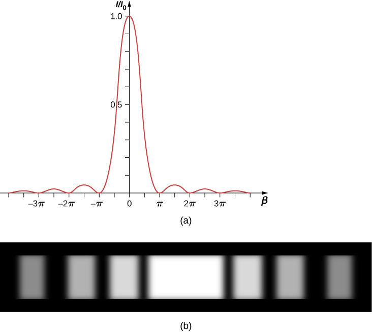
Light of wavelength 550 nm passes through a slit of width 2.00 μm and produces a diffraction pattern similar to that shown in Figure \(\PageIndex{3a}\).
- Find the locations of the first two minima in terms of the angle from the central maximum.
- Determine the intensity relative to the central maximum at a point halfway between these two minima.
Strategy
The minima are given by Equation 4.2.1, \(a \, sin \, \theta = m\lambda\). The first two minima are for m = 1 and m = 2. Equation \ref{eq20} and Equation \ref{4.2} can be used to determine the intensity once the angle has been worked out.
Solution
- Solving Equation 4.2.1 for θ gives us \(\theta_m = \sin^{-1}(m\lambda/a)\), so that
\[\theta_1 = \sin^{-1} \left(\dfrac{(+1)(550 \times 10^{-9} m)}{2.00 \times 10^{-6}m}\right) = +16.0° \nonumber \]
and\[\theta_2 = \sin^{-1} \left(\dfrac{(+2)(550 \times 10^{-9}m)}{2.00 \times 10^{-6}m}\right) = +33.4°. \nonumber \]
- The halfway point between \(\theta_1\) and \(\theta_2\) is
\[\theta = (\theta_1 + \theta_2) /2 = (16.0° + 33.4°)/2 = 24.7°. \nonumber \]
Equation \ref{4.2} gives
\[\beta = \dfrac{\pi a \, sin \, \theta}{\lambda} = \dfrac{\pi (2.00 \times 10^{-6}m) \, \sin \, (24.7°)}{(550 \times 10^{-9}m)} = 1.52\pi \, or \, 4.77 \, rad. \nonumber \]
From Equation \ref{eq20}, we can calculate
\[\dfrac{I}{I_0} = \left(\dfrac{\sin \, \beta}{\beta}\right)^2 = \left(\dfrac{\sin \, (4.77)}{4.77}\right)^2 = \left(\dfrac{-0.9985}{4.77}\right)^2 = 0.044. \nonumber \]
Significance
This position, halfway between two minima, is very close to the location of the maximum, expected near \(\beta = 3\pi/2\), or \(1.5\pi\).
For the experiment in Example \(\PageIndex{1}\), at what angle from the center is the third maximum and what is its intensity relative to the central maximum?
- Answer
-
\(74.3^o\), \(0.0083 I_0\)
If the slit width \(a\) is varied, the intensity distribution changes, as illustrated in Figure \(\PageIndex{4}\). The central peak is distributed over the region from \(sin \, \theta = -\lambda/a\) to \(sin \, \theta = +\lambda/a\). For small θ, this corresponds to an angular width \(\Delta \theta \approx 2\lambda /a\). Hence, an increase in the slit width results in a decrease in the width of the central peak. For a slit with a ≫ λ, the central peak is very sharp, whereas if a ≈ λ, it becomes quite broad.

A diffraction experiment in optics can require a lot of preparation but this simulation by Andrew Duffy offers not only a quick set up but also the ability to change the slit width instantly. Run the simulation and select “Single slit.” You can adjust the slit width and see the effect on the diffraction pattern on a screen and as a graph.


