11.3: The Law of Reflection
- Page ID
- 47075
\( \newcommand{\vecs}[1]{\overset { \scriptstyle \rightharpoonup} {\mathbf{#1}} } \)
\( \newcommand{\vecd}[1]{\overset{-\!-\!\rightharpoonup}{\vphantom{a}\smash {#1}}} \)
\( \newcommand{\dsum}{\displaystyle\sum\limits} \)
\( \newcommand{\dint}{\displaystyle\int\limits} \)
\( \newcommand{\dlim}{\displaystyle\lim\limits} \)
\( \newcommand{\id}{\mathrm{id}}\) \( \newcommand{\Span}{\mathrm{span}}\)
( \newcommand{\kernel}{\mathrm{null}\,}\) \( \newcommand{\range}{\mathrm{range}\,}\)
\( \newcommand{\RealPart}{\mathrm{Re}}\) \( \newcommand{\ImaginaryPart}{\mathrm{Im}}\)
\( \newcommand{\Argument}{\mathrm{Arg}}\) \( \newcommand{\norm}[1]{\| #1 \|}\)
\( \newcommand{\inner}[2]{\langle #1, #2 \rangle}\)
\( \newcommand{\Span}{\mathrm{span}}\)
\( \newcommand{\id}{\mathrm{id}}\)
\( \newcommand{\Span}{\mathrm{span}}\)
\( \newcommand{\kernel}{\mathrm{null}\,}\)
\( \newcommand{\range}{\mathrm{range}\,}\)
\( \newcommand{\RealPart}{\mathrm{Re}}\)
\( \newcommand{\ImaginaryPart}{\mathrm{Im}}\)
\( \newcommand{\Argument}{\mathrm{Arg}}\)
\( \newcommand{\norm}[1]{\| #1 \|}\)
\( \newcommand{\inner}[2]{\langle #1, #2 \rangle}\)
\( \newcommand{\Span}{\mathrm{span}}\) \( \newcommand{\AA}{\unicode[.8,0]{x212B}}\)
\( \newcommand{\vectorA}[1]{\vec{#1}} % arrow\)
\( \newcommand{\vectorAt}[1]{\vec{\text{#1}}} % arrow\)
\( \newcommand{\vectorB}[1]{\overset { \scriptstyle \rightharpoonup} {\mathbf{#1}} } \)
\( \newcommand{\vectorC}[1]{\textbf{#1}} \)
\( \newcommand{\vectorD}[1]{\overrightarrow{#1}} \)
\( \newcommand{\vectorDt}[1]{\overrightarrow{\text{#1}}} \)
\( \newcommand{\vectE}[1]{\overset{-\!-\!\rightharpoonup}{\vphantom{a}\smash{\mathbf {#1}}}} \)
\( \newcommand{\vecs}[1]{\overset { \scriptstyle \rightharpoonup} {\mathbf{#1}} } \)
\(\newcommand{\longvect}{\overrightarrow}\)
\( \newcommand{\vecd}[1]{\overset{-\!-\!\rightharpoonup}{\vphantom{a}\smash {#1}}} \)
\(\newcommand{\avec}{\mathbf a}\) \(\newcommand{\bvec}{\mathbf b}\) \(\newcommand{\cvec}{\mathbf c}\) \(\newcommand{\dvec}{\mathbf d}\) \(\newcommand{\dtil}{\widetilde{\mathbf d}}\) \(\newcommand{\evec}{\mathbf e}\) \(\newcommand{\fvec}{\mathbf f}\) \(\newcommand{\nvec}{\mathbf n}\) \(\newcommand{\pvec}{\mathbf p}\) \(\newcommand{\qvec}{\mathbf q}\) \(\newcommand{\svec}{\mathbf s}\) \(\newcommand{\tvec}{\mathbf t}\) \(\newcommand{\uvec}{\mathbf u}\) \(\newcommand{\vvec}{\mathbf v}\) \(\newcommand{\wvec}{\mathbf w}\) \(\newcommand{\xvec}{\mathbf x}\) \(\newcommand{\yvec}{\mathbf y}\) \(\newcommand{\zvec}{\mathbf z}\) \(\newcommand{\rvec}{\mathbf r}\) \(\newcommand{\mvec}{\mathbf m}\) \(\newcommand{\zerovec}{\mathbf 0}\) \(\newcommand{\onevec}{\mathbf 1}\) \(\newcommand{\real}{\mathbb R}\) \(\newcommand{\twovec}[2]{\left[\begin{array}{r}#1 \\ #2 \end{array}\right]}\) \(\newcommand{\ctwovec}[2]{\left[\begin{array}{c}#1 \\ #2 \end{array}\right]}\) \(\newcommand{\threevec}[3]{\left[\begin{array}{r}#1 \\ #2 \\ #3 \end{array}\right]}\) \(\newcommand{\cthreevec}[3]{\left[\begin{array}{c}#1 \\ #2 \\ #3 \end{array}\right]}\) \(\newcommand{\fourvec}[4]{\left[\begin{array}{r}#1 \\ #2 \\ #3 \\ #4 \end{array}\right]}\) \(\newcommand{\cfourvec}[4]{\left[\begin{array}{c}#1 \\ #2 \\ #3 \\ #4 \end{array}\right]}\) \(\newcommand{\fivevec}[5]{\left[\begin{array}{r}#1 \\ #2 \\ #3 \\ #4 \\ #5 \\ \end{array}\right]}\) \(\newcommand{\cfivevec}[5]{\left[\begin{array}{c}#1 \\ #2 \\ #3 \\ #4 \\ #5 \\ \end{array}\right]}\) \(\newcommand{\mattwo}[4]{\left[\begin{array}{rr}#1 \amp #2 \\ #3 \amp #4 \\ \end{array}\right]}\) \(\newcommand{\laspan}[1]{\text{Span}\{#1\}}\) \(\newcommand{\bcal}{\cal B}\) \(\newcommand{\ccal}{\cal C}\) \(\newcommand{\scal}{\cal S}\) \(\newcommand{\wcal}{\cal W}\) \(\newcommand{\ecal}{\cal E}\) \(\newcommand{\coords}[2]{\left\{#1\right\}_{#2}}\) \(\newcommand{\gray}[1]{\color{gray}{#1}}\) \(\newcommand{\lgray}[1]{\color{lightgray}{#1}}\) \(\newcommand{\rank}{\operatorname{rank}}\) \(\newcommand{\row}{\text{Row}}\) \(\newcommand{\col}{\text{Col}}\) \(\renewcommand{\row}{\text{Row}}\) \(\newcommand{\nul}{\text{Nul}}\) \(\newcommand{\var}{\text{Var}}\) \(\newcommand{\corr}{\text{corr}}\) \(\newcommand{\len}[1]{\left|#1\right|}\) \(\newcommand{\bbar}{\overline{\bvec}}\) \(\newcommand{\bhat}{\widehat{\bvec}}\) \(\newcommand{\bperp}{\bvec^\perp}\) \(\newcommand{\xhat}{\widehat{\xvec}}\) \(\newcommand{\vhat}{\widehat{\vvec}}\) \(\newcommand{\uhat}{\widehat{\uvec}}\) \(\newcommand{\what}{\widehat{\wvec}}\) \(\newcommand{\Sighat}{\widehat{\Sigma}}\) \(\newcommand{\lt}{<}\) \(\newcommand{\gt}{>}\) \(\newcommand{\amp}{&}\) \(\definecolor{fillinmathshade}{gray}{0.9}\)Learning Objectives
By the end of this section, you will be able to:
- Explain reflection of light from polished and rough surfaces.
Whenever we look into a mirror, or squint at sunlight glinting from a lake, we are seeing a reflection. When you look at this page, too, you are seeing light reflected from it. Large telescopes use reflection to form an image of stars and other astronomical objects.
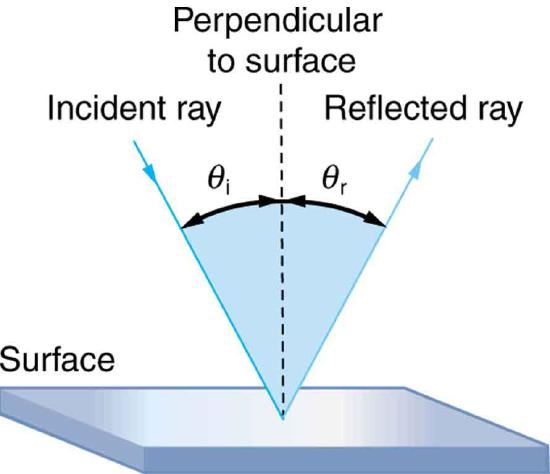
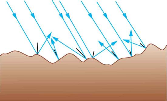
The law of reflection is illustrated in Figure \(\PageIndex{1}\), which also shows how the angles are measured relative to the perpendicular to the surface at the point where the light ray strikes. We expect to see reflections from smooth surfaces, but Figure \(\PageIndex{2}\) illustrates how a rough surface reflects light. Since the light strikes different parts of the surface at different angles, it is reflected in many different directions, or diffused.
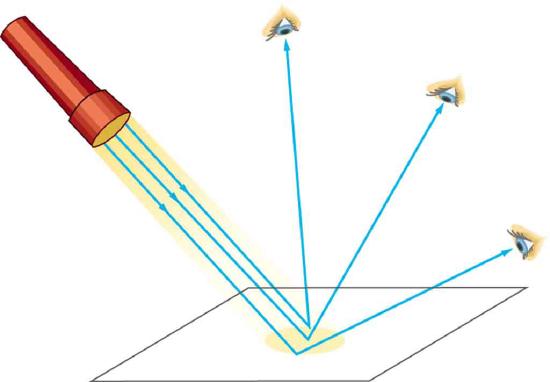
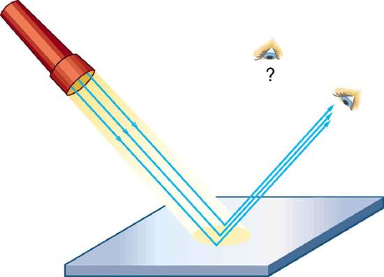
Diffused light is what allows us to see a sheet of paper from any angle, as illustrated in Figure \(\PageIndex{3a}\). Many objects, such as people, clothing, leaves, and walls, have rough surfaces and can be seen from all sides. A mirror, on the other hand, has a smooth surface (compared with the wavelength of light) and reflects light at specific angles, as illustrated in Figure \(\PageIndex{3b}\). When the moon reflects from a lake, as shown in Figure \(\PageIndex{4}\), a combination of these effects takes place.

The law of reflection is very simple: The angle of reflection equals the angle of incidence.
Definition: THE LAW OF REFLECTION
The angle of reflection equals the angle of incidence.
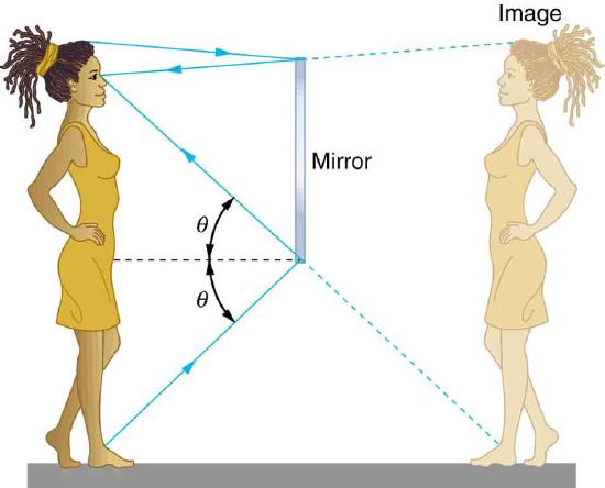
When we see ourselves in a mirror, it appears that our image is actually behind the mirror. This is illustrated in Figure \(\PageIndex{5}\). We see the light coming from a direction determined by the law of reflection. The angles are such that our image is exactly the same distance behind the mirror as we stand away from the mirror. If the mirror is on the wall of a room, the images in it are all behind the mirror, which can make the room seem bigger. Although these mirror images make objects appear to be where they cannot be (like behind a solid wall), the images are not figments of our imagination. Mirror images can be photographed and videotaped by instruments and look just as they do with our eyes (optical instruments themselves). The precise manner in which images are formed by mirrors and lenses will be treated in later sections of this chapter
TAKE-HOME EXPERIMENT: LAW OF REFLECTION
Take a piece of paper and shine a flashlight at an angle at the paper, as shown in Figure \(\PageIndex{5a}\). Now shine the flashlight at a mirror at an angle. Do your observations confirm the predictions in Figure \(\PageIndex{3}\)? Shine the flashlight on various surfaces and determine whether the reflected light is diffuse or not. You can choose a shiny metallic lid of a pot or your skin. Using the mirror and flashlight, can you confirm the law of reflection? You will need to draw lines on a piece of paper showing the incident and reflected rays. (This part works even better if you use a laser pencil.)
Summary
- The angle of reflection equals the angle of incidence.
- A mirror has a smooth surface and reflects light at specific angles.
- Light is diffused when it reflects from a rough surface.
- Mirror images can be photographed and videotaped by instruments.
Glossary
- mirror
- smooth surface that reflects light at specific angles, forming an image of the person or object in front of it
- law of reflection
- angle of reflection equals the angle of incidence
Contributors and Attributions
Paul Peter Urone (Professor Emeritus at California State University, Sacramento) and Roger Hinrichs (State University of New York, College at Oswego) with Contributing Authors: Kim Dirks (University of Auckland) and Manjula Sharma (University of Sydney). This work is licensed by OpenStax University Physics under a Creative Commons Attribution License (by 4.0).


