
4.7: Wrap-Up
- Page ID
- 27777

\( \newcommand{\vecs}[1]{\overset { \scriptstyle \rightharpoonup} {\mathbf{#1}} } \)
\( \newcommand{\vecd}[1]{\overset{-\!-\!\rightharpoonup}{\vphantom{a}\smash {#1}}} \)
\( \newcommand{\id}{\mathrm{id}}\) \( \newcommand{\Span}{\mathrm{span}}\)
( \newcommand{\kernel}{\mathrm{null}\,}\) \( \newcommand{\range}{\mathrm{range}\,}\)
\( \newcommand{\RealPart}{\mathrm{Re}}\) \( \newcommand{\ImaginaryPart}{\mathrm{Im}}\)
\( \newcommand{\Argument}{\mathrm{Arg}}\) \( \newcommand{\norm}[1]{\| #1 \|}\)
\( \newcommand{\inner}[2]{\langle #1, #2 \rangle}\)
\( \newcommand{\Span}{\mathrm{span}}\)
\( \newcommand{\id}{\mathrm{id}}\)
\( \newcommand{\Span}{\mathrm{span}}\)
\( \newcommand{\kernel}{\mathrm{null}\,}\)
\( \newcommand{\range}{\mathrm{range}\,}\)
\( \newcommand{\RealPart}{\mathrm{Re}}\)
\( \newcommand{\ImaginaryPart}{\mathrm{Im}}\)
\( \newcommand{\Argument}{\mathrm{Arg}}\)
\( \newcommand{\norm}[1]{\| #1 \|}\)
\( \newcommand{\inner}[2]{\langle #1, #2 \rangle}\)
\( \newcommand{\Span}{\mathrm{span}}\) \( \newcommand{\AA}{\unicode[.8,0]{x212B}}\)
\( \newcommand{\vectorA}[1]{\vec{#1}} % arrow\)
\( \newcommand{\vectorAt}[1]{\vec{\text{#1}}} % arrow\)
\( \newcommand{\vectorB}[1]{\overset { \scriptstyle \rightharpoonup} {\mathbf{#1}} } \)
\( \newcommand{\vectorC}[1]{\textbf{#1}} \)
\( \newcommand{\vectorD}[1]{\overrightarrow{#1}} \)
\( \newcommand{\vectorDt}[1]{\overrightarrow{\text{#1}}} \)
\( \newcommand{\vectE}[1]{\overset{-\!-\!\rightharpoonup}{\vphantom{a}\smash{\mathbf {#1}}}} \)
\( \newcommand{\vecs}[1]{\overset { \scriptstyle \rightharpoonup} {\mathbf{#1}} } \)
\( \newcommand{\vecd}[1]{\overset{-\!-\!\rightharpoonup}{\vphantom{a}\smash {#1}}} \)
\(\newcommand{\avec}{\mathbf a}\) \(\newcommand{\bvec}{\mathbf b}\) \(\newcommand{\cvec}{\mathbf c}\) \(\newcommand{\dvec}{\mathbf d}\) \(\newcommand{\dtil}{\widetilde{\mathbf d}}\) \(\newcommand{\evec}{\mathbf e}\) \(\newcommand{\fvec}{\mathbf f}\) \(\newcommand{\nvec}{\mathbf n}\) \(\newcommand{\pvec}{\mathbf p}\) \(\newcommand{\qvec}{\mathbf q}\) \(\newcommand{\svec}{\mathbf s}\) \(\newcommand{\tvec}{\mathbf t}\) \(\newcommand{\uvec}{\mathbf u}\) \(\newcommand{\vvec}{\mathbf v}\) \(\newcommand{\wvec}{\mathbf w}\) \(\newcommand{\xvec}{\mathbf x}\) \(\newcommand{\yvec}{\mathbf y}\) \(\newcommand{\zvec}{\mathbf z}\) \(\newcommand{\rvec}{\mathbf r}\) \(\newcommand{\mvec}{\mathbf m}\) \(\newcommand{\zerovec}{\mathbf 0}\) \(\newcommand{\onevec}{\mathbf 1}\) \(\newcommand{\real}{\mathbb R}\) \(\newcommand{\twovec}[2]{\left[\begin{array}{r}#1 \\ #2 \end{array}\right]}\) \(\newcommand{\ctwovec}[2]{\left[\begin{array}{c}#1 \\ #2 \end{array}\right]}\) \(\newcommand{\threevec}[3]{\left[\begin{array}{r}#1 \\ #2 \\ #3 \end{array}\right]}\) \(\newcommand{\cthreevec}[3]{\left[\begin{array}{c}#1 \\ #2 \\ #3 \end{array}\right]}\) \(\newcommand{\fourvec}[4]{\left[\begin{array}{r}#1 \\ #2 \\ #3 \\ #4 \end{array}\right]}\) \(\newcommand{\cfourvec}[4]{\left[\begin{array}{c}#1 \\ #2 \\ #3 \\ #4 \end{array}\right]}\) \(\newcommand{\fivevec}[5]{\left[\begin{array}{r}#1 \\ #2 \\ #3 \\ #4 \\ #5 \\ \end{array}\right]}\) \(\newcommand{\cfivevec}[5]{\left[\begin{array}{c}#1 \\ #2 \\ #3 \\ #4 \\ #5 \\ \end{array}\right]}\) \(\newcommand{\mattwo}[4]{\left[\begin{array}{rr}#1 \amp #2 \\ #3 \amp #4 \\ \end{array}\right]}\) \(\newcommand{\laspan}[1]{\text{Span}\{#1\}}\) \(\newcommand{\bcal}{\cal B}\) \(\newcommand{\ccal}{\cal C}\) \(\newcommand{\scal}{\cal S}\) \(\newcommand{\wcal}{\cal W}\) \(\newcommand{\ecal}{\cal E}\) \(\newcommand{\coords}[2]{\left\{#1\right\}_{#2}}\) \(\newcommand{\gray}[1]{\color{gray}{#1}}\) \(\newcommand{\lgray}[1]{\color{lightgray}{#1}}\) \(\newcommand{\rank}{\operatorname{rank}}\) \(\newcommand{\row}{\text{Row}}\) \(\newcommand{\col}{\text{Col}}\) \(\renewcommand{\row}{\text{Row}}\) \(\newcommand{\nul}{\text{Nul}}\) \(\newcommand{\var}{\text{Var}}\) \(\newcommand{\corr}{\text{corr}}\) \(\newcommand{\len}[1]{\left|#1\right|}\) \(\newcommand{\bbar}{\overline{\bvec}}\) \(\newcommand{\bhat}{\widehat{\bvec}}\) \(\newcommand{\bperp}{\bvec^\perp}\) \(\newcommand{\xhat}{\widehat{\xvec}}\) \(\newcommand{\vhat}{\widehat{\vvec}}\) \(\newcommand{\uhat}{\widehat{\uvec}}\) \(\newcommand{\what}{\widehat{\wvec}}\) \(\newcommand{\Sighat}{\widehat{\Sigma}}\) \(\newcommand{\lt}{<}\) \(\newcommand{\gt}{>}\) \(\newcommand{\amp}{&}\) \(\definecolor{fillinmathshade}{gray}{0.9}\)Simple Magnifier
When one thinks about lenses in the "real world," one of the first things that leaps to mind is the magnifying glass. With all of our discussion of lateral magnification in geometrical optics, it's tempting to think that explaining how a single lens facilitates seeing details of small objects should be simple. But it turns out that a full explanation is more complicated than one would think.
The first step in understanding the use of a "simple magnifier" (a single converging lens) is to return to the idea that seeing something better is a function of the fraction of one's field of view the object occupies. The angle subtended by the object is directly related to how big it looks. The angle subtended is a function of two things: the size of the object and its proximity to the viewer. Viewing objects through lenses results in images that differ from the object in both of these elements, so we cannot draw a conclusion about the effect of a magnifying glass on the basis of lateral magnification alone.
One way to "magnify" a small object does not even involve a lens – just bring it closer to your eye. The trouble is, the human eye can only observe a clear image that is beyond a certain distance – too close and it gets blurry. The ability to see close items varies from one person to the next, but the generally-accepted standard for the near point for human beings (the minimum distance where a clear image can be seen) is \(25cm\). So whatever lateral magnification we can artificially create optically, we can always make the image easier to see by moving it closer to our eye, up to a distance of \(25cm\).
Let's suppose we maximize this "natural" form of magnification for a naked eye. The biggest angle the item can subtend in our view can be easily calculated from the size of the object \(y\) and the \(25cm\) separation:
Figure 4.7.1 – Maximum "Magnification" for Naked Eye
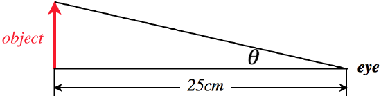
\[\tan\theta = \dfrac{y}{25cm} \]
So our goal is to use a lens to create a situation where the image subtends a larger angle than is indicated by the equation above, without that image being closer than \(25cm\) to the eye (which would make it impossible for a human to see clearly). There are three single-lens scenarios to choose from: The diverging lens (Figure 4.5.5), the real image converging lens (Figure 4.5.3), and the virtual image converging lens (Figure 4.5.4). Let's consider each possibility in turn.
The diverging lens actually has the opposite of the desired effect. The image is actually closer to the observer than the object, which means that the object must be placed at a distance greater than \(25cm\) from the observer. The ray trace in Figure 4.5.5 reveals that the angles subtended by the image and object is the same. This is evident from the fact that the ray that passes straight through the vertex of the lens also passes through the point of both image and object, creating similar triangles. With the object height still being \(y\) and the horizontal distance greater than \(25cm\), it's clear that the angle subtended is smaller for this case than if we simply look at the object directly, without the lens.
The real image created by a converging lens can laterally magnify the image as large as we like, and if we then observe this image from a distance of \(25cm\), the angle subtended can be arbitrarily large. While this works as a magnifier, it comes with some impractical aspects to it. The first is that the image is inverted, which can cause problems for applications like reading fine print. More importantly, to create a real image, the lens must be a distance from the object that it greater than the focal length of the lens, and the observer must be a distance from the lens that is at least the object distance plus \(25cm\). This is best illustrated with an actual calculation...
Suppose we have a lens with a focal length of \(f=+20cm\) (this is a "focusing power" of \(\frac{1}{0.2m} = 5\;diopters\)), and we want to magnify it so that it subtends twice the angle that it subtends when we look at it directly. Whether we look directly at the object or look at its real image, we will be doing so at a distance of \(25cm\), so what we need to do is laterally magnify the image by about a factor of 2. [Actually doubling the height doubles the tangent, but we still assume that the tangent of the angle is approximately equal to the angle.] The lateral magnification is 2 when the image distance is twice the object distance, \(s'=2s\). Putting these criteria into the thin lens equation gives:
\[\dfrac{1}{s}+\dfrac{1}{s'}=\dfrac{1}{f}\;\;\;\Rightarrow\;\;\;\dfrac{1}{s}+\dfrac{1}{2s}=\dfrac{1}{f}\;\;\;\Rightarrow\;\;\;s=\frac{3}{2}f =30cm \;\;\;\Rightarrow\;\;\; s'=3f=60cm\]
The observer must be an additional \(25cm\) from the lens to see this image clearly, which places the observer \(85cm\) from the lens and \(115cm\) from the object. Okay, so this can be accomplished, but the idea of getting an inverted \(2\times\) magnification from a distance of more than a meter from the object is not very practical. Let's look at the virtual image case of the converging lens.
Like the diverging lens, the object and image both subtend the same angle, but unlike the case of the diverging lens, it is the object that is closer to the observer. The observer's ability to focus on what it is seeing depends upon the image being at least \(25cm\) away. This means we can actually move the object closer than \(25cm\) from the observer, and since the angle subtended is determined by the height of the object and its distance from the observer, this allows the angle to get larger than it can without the lens present. What is more, unlike the case of the real image, the observer doesn't need to be any distance at all from the lens, as the image forms behind it.
Let's re-do the calculation for the \(5 diopter\) converging lens, this time using a virtual image. We want the image to be a distance of \(25cm\) from the observer, who can place their eye right up to the lens. This means that the image distance we want is just \(s'=-25cm\). From this we can solve for the object distance, and with that, the lateral magnification:
\[\dfrac{1}{s}+\dfrac{1}{-25cm}=\dfrac{1}{20cm}\;\;\;\Rightarrow\;\;\;s = 11.1cm \;\;\;\Rightarrow\;\;\; M=\dfrac{s'}{s} = \dfrac{25cm}{11.1cm} = 2.25\]
Given that the object and image form similar triangles, the angular magnification comes out approximately (\(\tan\theta\approx\theta\)) the same. So this gives us a magnification that is greater than \(2\times\), the image is upright, and the lens is only \(11cm\) from the object.
There is one advantage that comes with the real image method that is not available in the virtual image case, though it is not easy to implement. By adjusting the object distance closer to the focal length, the size of the image can be made as large as we like, which means that the observer can just look from a distance of \(25cm\) farther, and the amount of angular magnification can be made arbitrarily large for a given lens. For the virtual image case, we can increase the angle subtended by the image by moving the object closer to the lens, but doing so also moves the image closer to the lens (and observer). So this magnifier is limited to images that are \(25cm\) from the lens.
Converging lenses used for magnification are often labeled according to their magnifying power. When they are, the standard is usually the angular magnification when the object is placed at the focal point of the lens. That is, the magnifying power of a lens is the ratio of the angle subtended when the object is at the focal point and the angle subtended when no lens is used (and the object is at \(25cm\)). This comes out to just a simple ratio of the two object distances:
\[M_{magnifier}=\dfrac{\theta_{image\;with\;magnifier}}{\theta_{image\;at\;25cm}} \approx \dfrac{\tan\theta_{image\;with\;magnifier}}{\tan\theta_{image\;at\;25cm}} = \dfrac{\frac{y}{f}}{\frac{y}{25cm}} = \dfrac{25cm}{f}\]
Magnification Devices
Not surprisingly, a lens has greater magnifying power when its focal length is shorter. So suppose we have a rather powerful magnifier that we would like to use to view something very small or something very far away. In both cases, for the magnifier to work, we need to get the object a very small distance (less than the focal length) from the lens. This is difficult to do for very small objects because the tolerances are so small, and because it might be difficult to get light to the small object with the lens looming so close to it. And it is obviously impossible for distant objects.
The solution is to use two lenses. The first lens (known as the objective) has as its primary function the creation of a real image at a convenient position. Then the second lens (the eyepiece) functions as a simple magnifier that acts on that real image to increase the angle it subtends.
The device that magnifies small objects is of course a microscope. As a secondary function, the objective lens creates a laterally magnified real image, because the objective is pretty close to the object, while the real image it creates is farther away. Then the real image becomes an object for the eyepiece, which then magnifies it further (in the usual angular sense of a simple magnifier).
The device that magnifies distant objects is a telescope. Its objective lens's secondary function is to collect as much of the light as possible coming from the object (this explains why objective lenses are so much larger than the eyepieces). The object distance for the objective lens is very large and the image distance very small, so obviously it exhibits a tiny fractional lateral magnification and diminishes the image (stars are very large compared to their images). But this real image is then located very precisely at a position where the eyepiece can magnify the angle it subtends.
Odds and Ends
There are a number of interesting observations and side discussions about optics that don't fit well into the development of the subject that we will now address.
- light intensity – With all the geometry we do with straight-line rays, it's easy to forget that we are talking about light waves. Figure 4.6.1 expresses this wave nature in the context of geometrical optics fairly well, and just reminding ourselves of the wave nature in this way leads to some interesting ideas. Consider light intensity. If we have a plane wave of light coming into a converging lens parallel to the optical axis, what comes out the other side is a spherical wave that is collapsing down to the focal point. We already know that outwardly-moving spherical waves lose intensity as they move outward (the inverse-square law), so waves that are collapsing into a single point grow in intensity. This is why one can cause a piece of paper to light on fire with a magnifying glass in the sunlight. By placing the lens a distance equal to its focal length from the paper, all of the light energy passing through the lens is concentrated to a small region, raising the temperature to the combustion point.
- wave forms and standing waves – For many applications we discussed in physical optics, we required plane waves. We can get these by looking at a very distant source like the sun, but we can also do this locally by placing a point source at the focal point of a concave mirror. All the light that reflects off the mirror will come away from it parallel to the optical axis – plane waves. Lasers also figure prominently in our study of physical optics (thanks to their coherence), and one of the important elements in the design of lasers is something called a resonant cavity. This is essentially two spherical mirrors that cause the light to reflect back-and-forth, forming a standing wave, into which energy is pumped, and from which the beam emerges (like sound coming from a standing wave in an organ pipe).
- images have no substance – We have mentioned this already, but it bears repeating. When we do geometrical optics, the object and image arrows are both drawn in the ray trace, and in some sense are given equal status. But the object is an actual thing, made of atoms, while an image is a designated point in space where the light appears to be coming from. The thing that can get lost is that light only appears to be coming from that place if the actual light can be seen. Put in more visceral terms, an image created by a lens can only be seen if the observer looks through the lens! It sounds silly to have to say this, but in a ray trace diagram, one can see from any angle the image arrow that is drawn, and the notion that one must be looking in a specific direction is lost.
- projection onto a screen – Everyone knows that images can be projected onto a screen, but exactly how does that work? The first thing to note is that every position on the screen is associated with a single point on the image, which means that for a sharp image to occur, all the light from a single point on the object must converge to a single point on the screen, and from there it is reflected. This means that the screen must be placed exactly at the position of the image (the point where the rays converge is the definition of the position of the image). If the distance is off slightly, then light from nearby points on the object land at the same point. At any given point, most of the intruding light comes from nearby points, and this is perceived as blurring of the image. There is one other very important thing about projected images: It is not possible to project a virtual image onto a screen. The reason should be obvious – if a screen is placed where the rays converge for a virtual object, there is not actually any light there, so it cannot reflect off that screen.
- lens size – If we have two lenses of equal focal lengths, what is different about them if they are different sizes? One thing we don't tend to do is discuss the light that misses the lens and continues in its straight line. This light does not contribute to the image, which means that "collecting" more light with a larger lens only affects the brightness of the image. It perhaps seems strange that coating the left half of a lens with an opaque paint will not cut the image in half, but a dimmer version of the same image is what is seen.
Example \(\PageIndex{1}\)
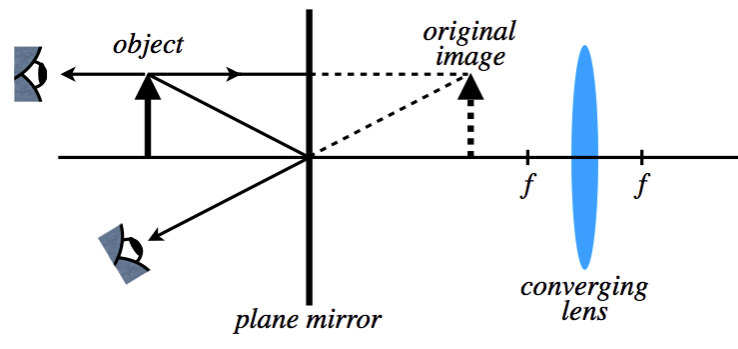
A ray trace for an object near a plane mirror is shown below. If a converging lens with the focal length shown is placed at the position indicated (two focal lengths from the position of the image), find the distance that the new image is from the original image.
- Solution
-
This problem points out how easy it is to get caught up in the geometry while losing sight of what is physically going on. The lens has been placed behind the mirror. Clearly this will not change in any way the image seen in the mirror. The "new" image will be the same as the original image.
Summary of Geometrical Optics Mathematics
To close this chapter, its useful to pull together all of the mathematical relations into one place, as it allows us to see familiar patterns that run through all of them. In particular, it is interesting to note how defining variables in certain ways has allowed us a great deal of economy, especially in the sign conventions.
\[\begin{array}{l} \text{reflecting surface:} && f=\dfrac{R}{2} && \dfrac{1}{s} + \dfrac{1}{s'} = \dfrac{1}{f} && M = -\dfrac{s'}{s} \\ \text{refracting surface:} && f=\dfrac{n_2}{n_2-n_1}R && \left(\dfrac{n_1}{n_2}\right)\dfrac{1}{s} + \dfrac{1}{s'} = \dfrac{1}{f} && M= -\dfrac{n_1}{n_2}\dfrac{s'}{s} \\ \text{lens:} && \dfrac{1}{f}=\left(n-1\right)\left(\dfrac{1}{R_1} - \dfrac{1}{R_2}\right) && \dfrac{1}{s} + \dfrac{1}{s'} = \dfrac{1}{f} && M = -\dfrac{s'}{s} \end{array}\]
\[\begin{array}{c} \text{name} && \text{symbol} && \text{positive when} && \text{negative when} \\ object\;distance && s && object\;on\;incoming\;side && object\;on\;other\;side \\ image\;distance && s' && image\;on\;outgoing\;side && image\;on\;other\;side \\ lateral\;magnification && M && image\;upright && image\;inverted \\ radius\;of\;curvature && R && center\;of\;sphere\;on\;outgoing\;side && center\;of\;sphere\;on\;other\;side \\ focal\;length && f && focal\;point\;on\;outgoing\;side && focal\;point\;on\;other\;side \end{array}\]
Looking at these, we can draw the following conclusions for cases involving single optical devices only (when an image for one device can become an object for a second device, these don't necessarily apply):
- Object distances are positive.
- When an image is virtual, its image distance is negative, which makes the magnification positive, so virtual images are upright and real images are inverted.
- Converging devices can produce real or virtual images (real when \(s>f\), virtual when \(s<f\)), while diverging devices can only produce virtual images. This follows from the sign of the focal length and the fact that object distances are positive.
- Diverging devices (diverging lenses and convex mirrors) produce diminished images (which, as stated above, must be upright and virtual), since the negative value of \(f\) and positive value of \(s\) requires that \(s'\) is smaller in magnitude than \(s\).