
5.5: Resistors in Parallel and Series
- Page ID
- 17164

\( \newcommand{\vecs}[1]{\overset { \scriptstyle \rightharpoonup} {\mathbf{#1}} } \)
\( \newcommand{\vecd}[1]{\overset{-\!-\!\rightharpoonup}{\vphantom{a}\smash {#1}}} \)
\( \newcommand{\dsum}{\displaystyle\sum\limits} \)
\( \newcommand{\dint}{\displaystyle\int\limits} \)
\( \newcommand{\dlim}{\displaystyle\lim\limits} \)
\( \newcommand{\id}{\mathrm{id}}\) \( \newcommand{\Span}{\mathrm{span}}\)
( \newcommand{\kernel}{\mathrm{null}\,}\) \( \newcommand{\range}{\mathrm{range}\,}\)
\( \newcommand{\RealPart}{\mathrm{Re}}\) \( \newcommand{\ImaginaryPart}{\mathrm{Im}}\)
\( \newcommand{\Argument}{\mathrm{Arg}}\) \( \newcommand{\norm}[1]{\| #1 \|}\)
\( \newcommand{\inner}[2]{\langle #1, #2 \rangle}\)
\( \newcommand{\Span}{\mathrm{span}}\)
\( \newcommand{\id}{\mathrm{id}}\)
\( \newcommand{\Span}{\mathrm{span}}\)
\( \newcommand{\kernel}{\mathrm{null}\,}\)
\( \newcommand{\range}{\mathrm{range}\,}\)
\( \newcommand{\RealPart}{\mathrm{Re}}\)
\( \newcommand{\ImaginaryPart}{\mathrm{Im}}\)
\( \newcommand{\Argument}{\mathrm{Arg}}\)
\( \newcommand{\norm}[1]{\| #1 \|}\)
\( \newcommand{\inner}[2]{\langle #1, #2 \rangle}\)
\( \newcommand{\Span}{\mathrm{span}}\) \( \newcommand{\AA}{\unicode[.8,0]{x212B}}\)
\( \newcommand{\vectorA}[1]{\vec{#1}} % arrow\)
\( \newcommand{\vectorAt}[1]{\vec{\text{#1}}} % arrow\)
\( \newcommand{\vectorB}[1]{\overset { \scriptstyle \rightharpoonup} {\mathbf{#1}} } \)
\( \newcommand{\vectorC}[1]{\textbf{#1}} \)
\( \newcommand{\vectorD}[1]{\overrightarrow{#1}} \)
\( \newcommand{\vectorDt}[1]{\overrightarrow{\text{#1}}} \)
\( \newcommand{\vectE}[1]{\overset{-\!-\!\rightharpoonup}{\vphantom{a}\smash{\mathbf {#1}}}} \)
\( \newcommand{\vecs}[1]{\overset { \scriptstyle \rightharpoonup} {\mathbf{#1}} } \)
\(\newcommand{\longvect}{\overrightarrow}\)
\( \newcommand{\vecd}[1]{\overset{-\!-\!\rightharpoonup}{\vphantom{a}\smash {#1}}} \)
\(\newcommand{\avec}{\mathbf a}\) \(\newcommand{\bvec}{\mathbf b}\) \(\newcommand{\cvec}{\mathbf c}\) \(\newcommand{\dvec}{\mathbf d}\) \(\newcommand{\dtil}{\widetilde{\mathbf d}}\) \(\newcommand{\evec}{\mathbf e}\) \(\newcommand{\fvec}{\mathbf f}\) \(\newcommand{\nvec}{\mathbf n}\) \(\newcommand{\pvec}{\mathbf p}\) \(\newcommand{\qvec}{\mathbf q}\) \(\newcommand{\svec}{\mathbf s}\) \(\newcommand{\tvec}{\mathbf t}\) \(\newcommand{\uvec}{\mathbf u}\) \(\newcommand{\vvec}{\mathbf v}\) \(\newcommand{\wvec}{\mathbf w}\) \(\newcommand{\xvec}{\mathbf x}\) \(\newcommand{\yvec}{\mathbf y}\) \(\newcommand{\zvec}{\mathbf z}\) \(\newcommand{\rvec}{\mathbf r}\) \(\newcommand{\mvec}{\mathbf m}\) \(\newcommand{\zerovec}{\mathbf 0}\) \(\newcommand{\onevec}{\mathbf 1}\) \(\newcommand{\real}{\mathbb R}\) \(\newcommand{\twovec}[2]{\left[\begin{array}{r}#1 \\ #2 \end{array}\right]}\) \(\newcommand{\ctwovec}[2]{\left[\begin{array}{c}#1 \\ #2 \end{array}\right]}\) \(\newcommand{\threevec}[3]{\left[\begin{array}{r}#1 \\ #2 \\ #3 \end{array}\right]}\) \(\newcommand{\cthreevec}[3]{\left[\begin{array}{c}#1 \\ #2 \\ #3 \end{array}\right]}\) \(\newcommand{\fourvec}[4]{\left[\begin{array}{r}#1 \\ #2 \\ #3 \\ #4 \end{array}\right]}\) \(\newcommand{\cfourvec}[4]{\left[\begin{array}{c}#1 \\ #2 \\ #3 \\ #4 \end{array}\right]}\) \(\newcommand{\fivevec}[5]{\left[\begin{array}{r}#1 \\ #2 \\ #3 \\ #4 \\ #5 \\ \end{array}\right]}\) \(\newcommand{\cfivevec}[5]{\left[\begin{array}{c}#1 \\ #2 \\ #3 \\ #4 \\ #5 \\ \end{array}\right]}\) \(\newcommand{\mattwo}[4]{\left[\begin{array}{rr}#1 \amp #2 \\ #3 \amp #4 \\ \end{array}\right]}\) \(\newcommand{\laspan}[1]{\text{Span}\{#1\}}\) \(\newcommand{\bcal}{\cal B}\) \(\newcommand{\ccal}{\cal C}\) \(\newcommand{\scal}{\cal S}\) \(\newcommand{\wcal}{\cal W}\) \(\newcommand{\ecal}{\cal E}\) \(\newcommand{\coords}[2]{\left\{#1\right\}_{#2}}\) \(\newcommand{\gray}[1]{\color{gray}{#1}}\) \(\newcommand{\lgray}[1]{\color{lightgray}{#1}}\) \(\newcommand{\rank}{\operatorname{rank}}\) \(\newcommand{\row}{\text{Row}}\) \(\newcommand{\col}{\text{Col}}\) \(\renewcommand{\row}{\text{Row}}\) \(\newcommand{\nul}{\text{Nul}}\) \(\newcommand{\var}{\text{Var}}\) \(\newcommand{\corr}{\text{corr}}\) \(\newcommand{\len}[1]{\left|#1\right|}\) \(\newcommand{\bbar}{\overline{\bvec}}\) \(\newcommand{\bhat}{\widehat{\bvec}}\) \(\newcommand{\bperp}{\bvec^\perp}\) \(\newcommand{\xhat}{\widehat{\xvec}}\) \(\newcommand{\vhat}{\widehat{\vvec}}\) \(\newcommand{\uhat}{\widehat{\uvec}}\) \(\newcommand{\what}{\widehat{\wvec}}\) \(\newcommand{\Sighat}{\widehat{\Sigma}}\) \(\newcommand{\lt}{<}\) \(\newcommand{\gt}{>}\) \(\newcommand{\amp}{&}\) \(\definecolor{fillinmathshade}{gray}{0.9}\)Up to this points we have mostly treated resistance as some general value in a given circuit or segment of a flow system, whether fluid or electric. Sometimes, however, it is useful to look deeper at individual elements in a flow system which have high resistance. In fluid circuits you might have section of a pipe with different resistance values. In an electric circuit, for example, we often have more than one light bulb which act as resistors. These light bulbs might have difference resistance and they might be wired in various way that we will shortly see. In addition, we have only considered a flow system, where there is only one possible path for the current. Here we will consider more complex system where the current has multiple paths such as a fluid channel that splits into several channels, or circuit wiring that allows current to flow along different wires.
Resistors in Series
When two or more resistors (whether they are electric elements or different section of a pipe) have the same amount of current flowing through them, the resistors are in series. In other words, the current that flows through the first resistor follows the same path to flow through the remaining resistors that are all in series. An example in Figure 5.5.1 below shows an electric circuit with two resistors and an analogous fluid circuit where two sections of a pipe have different resistances.
Figure 5.5.1: Resistors in Series.
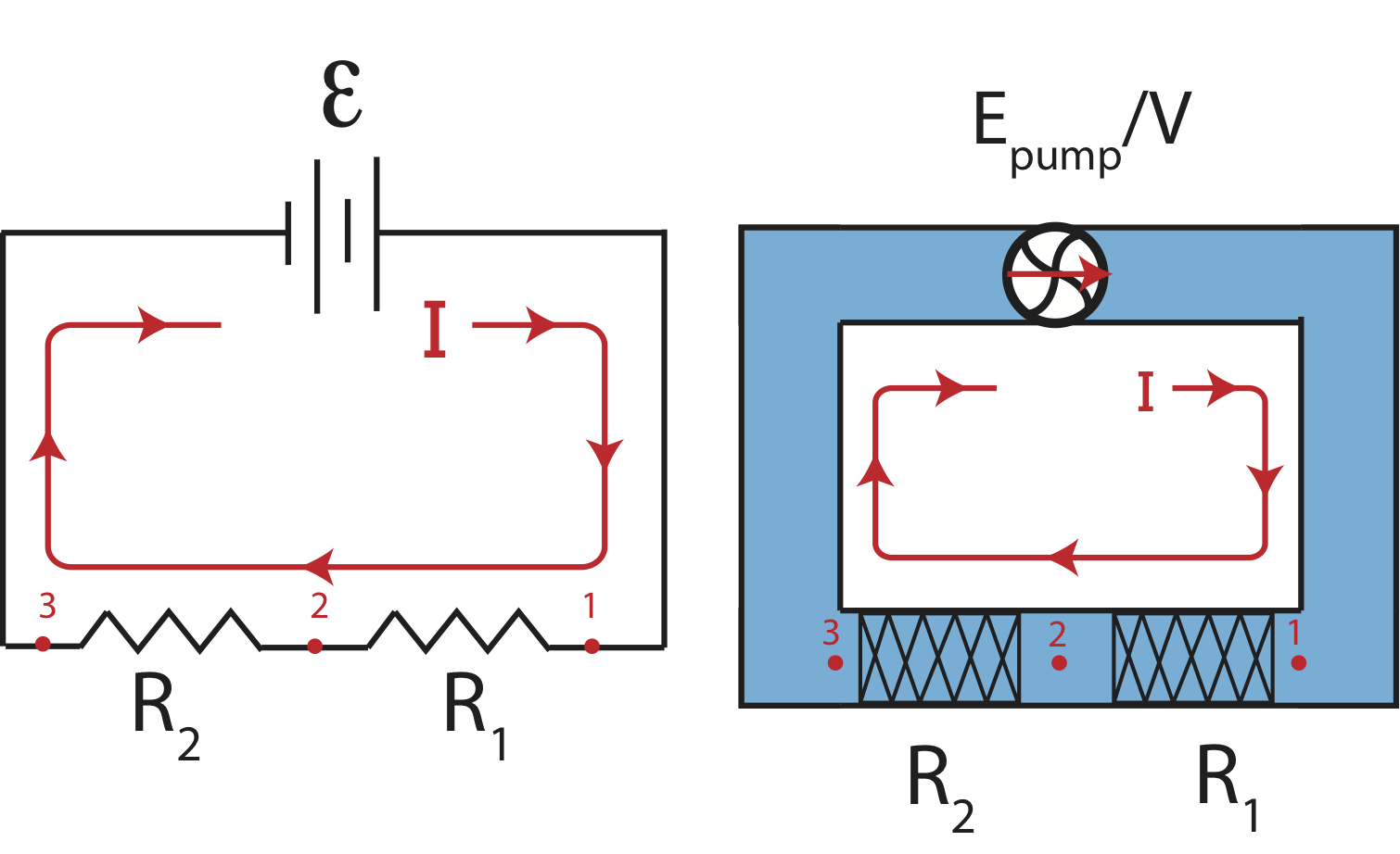
Our goal is to figure out how the individual resistances, \(R_1\) and \(R_2\), are related to the overall resistance of the entire circuit. This combined resistance is known as the equivalent resistance. It implies that if we were to replace all the resistors with one equivalent resistor it would have the same effect, or result in the same current, as the individual resistors. We assume that for both circuits the resistance is zero elsewhere in the circuit, the wires or other sections of the pipe. Let us analyzing the electric circuit first between points 1 and 2 and then between points 1 and 3:
\[V_2-V_1=-IR_1\]
\[V_3-V_2=-IR_2\]
Adding the two equation gives us the voltage drop across both resistors:
\[V_3-V_1=-I(R_1+R_2)\label{ser1}\]
Let us replace the two resistors by an equivalent resistor, \(R_{eq}\) as shown in the Figure 5.5.2 below.
Figure 5.5.2: Equivalent Resistance in Series.
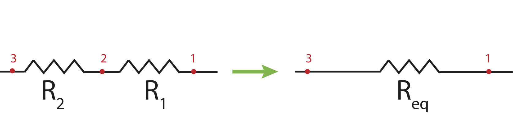
Finding the voltage drop across the equivalent resistor:
\[V_3-V_1=-IR_{eq}\label{ser2}\]
and combining Equations \ref{ser1} and \ref{ser2} we get the following expression for combing resistors in series:
\[R_{eq}=R_1+R_2\]
More generally, for an \(n\) number of resistors in series, the equivalent resistance is:
\[R_{eq}=\sum_i^n R_i\]
Resistors in Parallel
There is another way in which resistors can be arranged in a circuit, known as parallel resistors as depicted in Figure 5.5.3 below. Once we understand how the current flows when resistors are in parallel, we will see advantages of wiring resistors in this manner.
Figure 5.5.3: Resistors in Parallel.
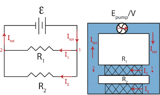
In the electric circuit in Figure 5.5.3 we see that a total current, \(I_{tot}\), reaching a point \(1\) after which there are two path for the current to travel, either through resistor \(R_1\) or resistor \(R_2\). This location in a circuit where the current is able to split is known as a junction. This circuit still describes steady-state electric flow, thus the current has to be constant. This implies that when the current splits into two paths the sums of the currents in the individual paths have to add to the current coming in:
\[I_{tot}=I_1+I_2\label{Icons}\]
Likewise, the current coming out of the junction as points \(2\) has to equal to the current, \(I_{tot}\) that entered the junction at \(1\). In other words, since current is conserved, the amount of current leaving the battery has to equal to the amount of current coming back to the battery. This is analogously true to the fluid circuit where the current splits into two separate pipes at a junction \(1\) and recombines at junction \(2\).
Another concept that could be applied here is the fact that when you apply the transport equation around the circuit as we did in Section 5.4 the change in energy-density has to be zero around the entire circuit. If we applied this concept to the upper path in Figure 5.5.3, following the current that goes through \(R_1\), we find that going this way, say from point \(1\), through \(R_1\), through the battery, and back to point \(1\) give us:
\[-\Delta V_1+\mathcal E=0\label{path1}\]
Similarly, if we follow the lower path in Figure 5.5.3, from point \(1\), through \(R_2\), through the battery, and back to point \(1\) we get:
\[-\Delta V_2+\mathcal E=0\label{path2}\]
Combining Equations \ref{path1} and \ref{path2} we get:
\[\Delta V_1=\Delta V_2\label{IR-parallel}\]
This bring us to the definition of parallel resistors:
1. The sum of the currents through each parallel resistor adds to the total current going into a junction where the current splits.
2. The voltage drop across resistors that are in parallel is the same.
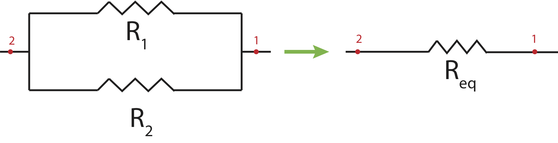
Our next goal is to figure out how to determine an equivalent resistance for parallel resistors. In other words, if we were to replace two parallel resistors \(R_1\) and \(R_2\) as shown in Figure 5.5.4 below by an equivalent resistor \(R_{eq}\) how would their resistances be related?
Figure 5.5.4: Equivalent Resistance in Parallel.
Rewriting Equation \ref{IR-parallel} in terms of currents and resistances we find:
\[I_1R_1=I_2R_2\label{paths}\]
This results tells us that the path with larger resistance will have smaller current and vice versa. Intuitively, it is logical that the path that has least resistance will get more current. Think about the fluid circuit in Figure 5.5.3. When the fluid reaches the junction a point \(1\), there are two paths to go. If one of the paths contains a narrow and mostly clogged pipe with high resistance, naturally, majority of the fluid will choose the other path. This is consistent with the result in Equation \ref{paths}.
Figure 5.5.4 shows the replacement of parallel resistors \(R_1\) and \(R_2\) with \(R_{eq}\). For resistors in series, the equivalent resistor has the same current as the two original resistors. Here, for the same argument that led us to Equation \ref{IR-parallel}, the voltage across the equivalent resistors is the same as the voltage across the original parallel resistors.
The current that goes through \(R_{eq}\) is the same as the current that enters the junction in the original circuit. Using \(\Delta V=-IR\) to rewrite current conservation, \(I_{eq}=I_1+I_2\), in terms of voltage drops we get:
\[\dfrac{\Delta V_{eq}}{R_{eq}}=\dfrac{\Delta V_{1}}{R_{1}}+\dfrac{\Delta V_{2}}{R_{2}}\]
Since the voltage drops are the same for both resistors and the equivalent resistor the above equation simplifies to:
\[\dfrac{1}{R_{eq}}=\dfrac{1}{R_1}+\dfrac{1}{R_2}\]
More generally, for an \(n\) number of resistors in parallel, the equivalent resistance is:
\[\dfrac{1}{R_{eq}}=\sum_i^n \dfrac{1}{R_i}\]
Generalized Rules
Kirchhoff Loop Rule: for any complete loop in a circuit (no matter how complicated the path appears, and how many batteries and resistors are in the loop), the total increase in potential caused by the emf of batteries or generators must equal the total voltage drops caused by all resistors in the loop. This loop rule in electricity is a formal statement of energy-density conservation. Mathematically the loop rule is written as:
\[\Delta V_{\text{loop}}=\sum\mathcal E-\sum IR=0\]
Kirchhoff Junction Rule: the sum of currents going into a junction has to equal to the sum of currents coming out of a junction. This junction rule in electricity is a formal statement of conservation of current. Mathematically the loop rule is written as:
\[\sum I_{in}=\sum I_{out}\]
Example \(\PageIndex{1}\)
Shown below is a circuit with multiple resistors.
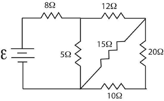
Find the equivalent resistance, \(R_{eq}\), for this circuit.
- Solution
-
Let's think about the path the current takes. After leaving the battery the first junction is after the \(8\Omega\) resistor. The current splits and part of it goes through the \(12\Omega\) resistor and part through the \(5\Omega\) resistor and back to the battery. The fraction of current that went through the \(12\Omega\) resistor meets another junction, such that part of that current goes through \(15\Omega\) resistor. Another part goes through the \(20\Omega\), which also goes through the \(10\Omega\) resistor. It is not always obvious in which order to combine resistors, and sometimes there are several ways of doing it. One rule of thumb is if there is a resistor parallel to multiple resistors in series, you need to combine the series resistors first. Thus, let us start with combining the \(20\Omega\) and the \(10\Omega\) resistors, calling the combination \(R_{1,eq}= 20\Omega+ 10\Omega=30\Omega\). After this step the circuit simplified to the following diagram.
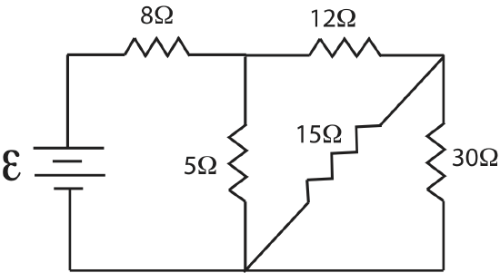
Now recall the current split after the \(12\Omega\) resistor, so the \(15\Omega\) resistor is parallel to the now combined \(30\Omega\) resistor. To make it simpler to visualize since the \(15\Omega\) resistor is drawn in a diagonal manner, we can redraw the above circuit like this.
Now it is more clear that \(15\Omega\) and \(30\Omega\) resistors are in parallel. Let us call their combined resistance, \(R_{2,eq}\):
\(\dfrac{1}{R_{2,eq}}=\dfrac{1}{15 \Omega}+\dfrac{1}{30 \Omega}=\dfrac{1}{10\Omega}\)
\(R_{2,eq}=10\Omega\)
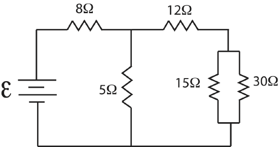
The further simplified circuit looks like the following diagram.
The \(12\Omega\) and \(10\Omega\) resistors are in series, \(R_{3,eq}= 12\Omega+ 10\Omega=22\Omega\). The simplified circuit now looks like this:
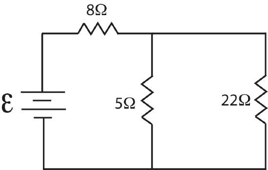
Next, we see that \(5\Omega\) and \(22\Omega\) resistors are in parallel:
\(\dfrac{1}{R_{4,eq}}=\dfrac{1}{5 \Omega}+\dfrac{1}{22\Omega}=0.245\dfrac{1}{\Omega}\)
\(R_{4,eq}=4.1\Omega\)
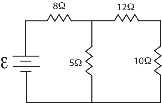
The diagram is now:
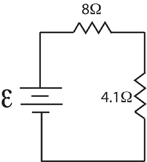
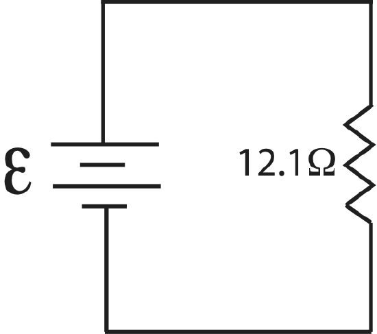
And finally combing the two remaining resistor in series, we obtain the equivalent resistance of this circuit, \(R_{eq}=8\Omega+4.1\Omega=12.1\Omega\).
Special Cases
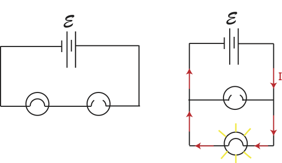
You must have heard the expression "short circuit" before, which you most likely associate with something going wrong with electronics, possible leading to overheating and electric sparks. We will now describe what a "short circuit" is using our developed circuit analysis tools. Imagine that you initially built a circuit with a battery and either two light bulbs in series as in the left diagram in Figure 5.5.5 or with two light bulbs in parallel as on the right diagram below (the circle with the curved line inside is a standard symbol for a light bulb). While wiring these circuits by mistake an extra wire is added across a resistor as drawn below.
Figure 5.5.5: Shorted Resistor.
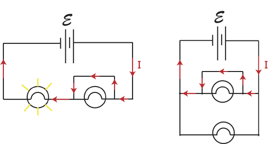
Let us carefully what what happens in this case. We know that wire have nearly zero resistance, and as a result there is no voltage drop across a wire. We also know that when things are wired in parallel, the voltage drops across each element are the same to conserve energy. If the voltage drop across the wire is zero, that means that the voltage drop across the light bulb parallel to the wire has to be zero as well. The only way for the voltage across a resistor to be zero is if there is no current going through that resistor due to \(\Delta V =-IR\). Another way to look at this is to refer back to Equation \label{paths} which tells us the relative currents when they are split at a junction. In this case, there is one path that has zero resistance, implying that all the current will go through that path and none through the path with resistance.
This path of the current with the extra wire is depicted with arrows in each circuit in Figure 5.5.5. In the left circuit one of the light bulbs with the wire across it will not be lit since all the current goes through the added wire. But all the current still goes through the second light bulb to return to the battery. It is as if the added wire removed that light bulbs completely, leaving a simple circuit with one lit light bulb. Thus, the first light bulb was shorted out. Also, an important thing to note is that when the wire is added the value of the total current coming out of the battery changes since the equivalent resistance of the circuit decreases from, \(R_1+R_2\) to just \(R_1\). A decrease in resistance means that the total current increased, since \(I=\mathcal E/R_{eq}\). Since the current increased more current will flow through the one lit light bulb, and it will be brighter compared to the original circuit since, \(P=I^2R\). The more power dissipated through the light bulb, the brighter it will shine.
For the circuit on the right in Figure 5.5.5 the wire is again placed across one of the light bulbs. In this case the current has three paths to chose from, the wire, and the two paths with a light bulb. Since current chooses the path with least resistance and the wire has zero resistance, all of the current will go through the wire, and both light bulbs will not be lit. What we are left with is a battery connected directly to a wire with extremely low resistance implying that the current is extremely high. This large current may result in the wire heating up or even catching on fire, and is clearly not a safe situation. This is the scenario which is known as short circuit.
The two scenarios below depict another situation where one of the light bulbs burns out.
When a light bulb burns out, the connection is broken, and current can no longer flow along that path. In the circuit with two light bulbs in series, the current only has one path, and since there is no longer a closed circuit, both light bulbs will not be lit. This is reason that in old-fashioned Christmas lights the entire row of lights would not be lit if even just one light burnt out, making it impossible to know easily which light to change. Now there are more clever mechanisms to deal with this problem.
In the circuit with parallel light bulbs, on the other hand, the current will still have a closed path with through the other light bulb as shown in the figure. Thus, the unburned light bulb will stay lit. In addition, the burnt out light bulb will not change the brightness, or power dissipated, of the second light bulb in the circuit with two parallel light bulbs. Why would this be since the total resistance of the circuit changes from \(R/2\) (if both light bulbs have equal resistance) to \(R\). In the original circuit, the total current was \(I=2\mathcal E/R\) but it split in half, each light bulb getting a current of \(\mathcal E/R\). That is exactly the amount of current the lit light bulb receives when the one of the light bulbs burns out, since the circuit is reduced to a simple circuit with a battery and a resistor. Or if you simply apply the loop rule, you can see that the burning of one light bulb does not change the bottom loop, resulting in, \(\mathcal E - \Delta V =0\).
If batteries are hooked up in series, their internal resistance (if any) will add, just as do their emfs. For example, four "AA" cells of 1.5 volts each used in series used in some electronic device would have a total emf 6 volts, but will also have four times the internal resistance of one cell. Because of its larger size, a “D” cell, while still having an emf of 1.5 V, will have considerable less internal resistance than will a “AA” cell.
When similar size batteries are wired in parallel in a circuit, the voltage across each battery will be the same (since they are hooked together with low resistance wire. The potential drop across each is the same. But their internal resistance and actual values of \(\mathcal E\), will determine how much current gets into the rest of the circuit and how much is “wasted” “going around in circles” among the batteries. In general, it is not a good idea to hook up batteries in parallel.