2.5: Applications of Newton's Laws


- Last updated
- Jan 28, 2023
- Save as PDF

( \newcommand{\kernel}{\mathrm{null}\,}\)
Consolidating What We Know So Far
We will now take a section to spend some time applying Newton's laws to some common circumstances. These applications will require a good understanding of what we have seen so far, but they are still fairly "basic" in the sense that they do not incorporate complications called "constraints," which we will put off discussing until next section. We'll start by tying up a couple of loose ends related to air resistance and friction, and then move on to some examples the reader can analyze to "grow their muscles" in understanding how Newton's laws are applied.
Air Resistance on Falling Objects
We already know something about gravity from our study of free-fall and projectile motion. We know that the acceleration is the same for objects of different masses. While we have used this as a model, it is a big step to claim that gravity fundamentally follows this rule. We know that a feather will experience the same acceleration due to gravity as a stone, if air resistance is removed. Now how do we put air resistance back into our model so that the reduced acceleration of the feather makes sense?
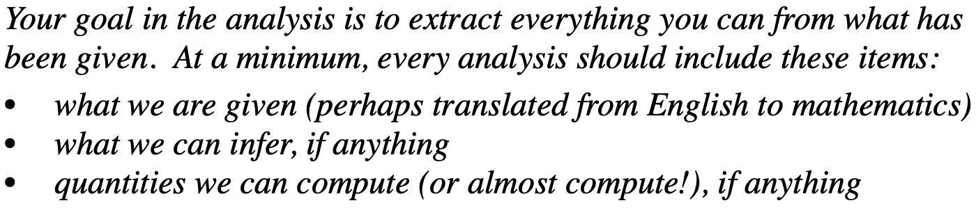
The effect of reduced acceleration is easy to show with a free-body diagram of two objects that are identical except for mass and are falling through the air and happen to be at the same speed. For these two objects the air resistance forces are equal, and the gravity force is greater on the heavier object. The net forces on the two objects are therefore different, giving the following accelerations:
a(heavy)=Fgravity(heavy)−Fdragm(heavy)a(light)=Fgravity(light)−Fdragm(light)Fgravity=mg}⇒a(heavy)=g−Fdragm(heavy)a(light)=g−Fdragm(light)
So the reason the heavier mass accelerates more is simply that the effect that the air resistance force has on it is smaller. From these final equations, we see that in the special case of assuming zero drag, we find that the acceleration happens to equal the constant g for objects of any mass.
Alert
It is important to understand that here g has a different meaning than it had when we were discussing motion involving gravity-caused acceleration. Here the g is a physical constant, which we use to determine the gravity force on an object with mass m. It does not mean that the object is accelerating at 9.8ms2! When an object experiences no other force than gravity, the object's acceleration just happens to equal this constant, but the constant is present regardless of the state of acceleration of the object.
An object accelerating in free-fall keeps moving faster with time, which means that the drag force due to the air keeps increasing (drag is a function of the speed through the fluid). This increase of speed cannot maintain the same rate forever, because eventually the speed will be great enough that the drag force will equal the gravity force. When this occurs, the two opposing forces cancel, and the second law tells us that acceleration must cease! What actually happens as the object falls is that the drag force gradually increases as the speed increases, gradually decreasing the falling object's acceleration. We will not go into the calculus that gives the resulting equation of motion, but instead will jump to the point where the acceleration diminishes to essentially zero. The speed at which this occurs is called terminal velocity. Clearly this velocity is determined by the many factors that go into the drag and gravitation forces.
Two spherical objects of identical radii but different masses are dropped from different heights through the air. They both reach terminal velocity at the same moment in time, and at that moment, they are side-by-side.
- Analysis
-
Start with a free-body diagram:
At terminal velocity, the object is no longer accelerating, which means that the net force on the object is zero. The only forces on these objects are gravity and air drag, so these opposing forces must be equal. The heavier object has a greater gravity force on it, so it must be also experiencing a greater drag force. The two objects have the same cross-sectional areas drag coefficients, and they are falling through the same air. This means that the only quantity that can account for their different drag forces is their speeds. Applying Newton's second law and noting that with velocity being the only variable to account for the difference in forces, we have:
Fd=Mg⇒M=Fdg∝V2terminal,fd=mg⇒m=fdg∝v2terminal
The most direct conclusion that we can derive from this is that the ratio of their terminal velocities in terms of the ratio of their masses is:
Vterminalvterminal=√Mm
It should also be noted that although these two spheres may be at the same height at the moment they each reach terminal velocity, they will not continue to remain side-by-side, since the heavier one is moving faster than the lighter one.
Slowing Motion with Friction
If a book is slid across a horizontal tabletop, it slows because there is a net force on it. The free-body diagram reveals that this net force comes from the kinetic friction force on the bottom of the book by the table surface. In our discussion of static vs. kinetic friction, we said that the maximum possible static friction force is greater than the kinetic friction force for the same two surfaces. That means that if the book we are sliding could somehow experience the maximum static friction force, then according to the second law, it would slow down faster. But how is one to accomplish this, given that the book must be sliding across the surface (the definition of kinetic friction) in order to be moving at all?
Okay, so maybe it is impossible to use static friction to slow a sliding book, but consider slowing an automobile (something we might be very interested in being able to slow as quickly as possible). What slows a car is the friction force on its tires by the road. Unlike the sliding book, the tires roll, unless we "lock up" the brakes. The interesting thing about rolling tires is that they are moving, but are not sliding. When breaks are applied, a friction force is introduced to the tires, but if they keep rolling and don't start skidding, then this force is static friction. The harder the brakes are applied, the greater this static friction force becomes. If the maximum value of static friction is exceeded, then the tires stop rolling and they start skidding across the surface. The friction force on the tires goes down when this occurs, because the kinetic friction is smaller than the maximum static friction. So anti-lock braking systems (ABS) common in today's automobiles automatically release the breaks briefly so that the tires again turn, restoring rolling and allowing the return of static friction. This would be like trying to push a heavy cardboard box across a floor in extremely short bursts – as soon as the box starts sliding (and gets easier to push), you stop and start over. Before the invention of ABS, drivers were told to "lightly pump their brakes" in slippery situations to create this same effect. ABS does the pumping for us, with a much greater frequency than we could manage, and to great effect.
Practice
What follows is a series of "Analyze This" boxes, intended to give the reader some practice employing Newton's laws (and especially the second law). These examples come in several types:
- direct applications of Newton's laws to draw conclusions about forces
- bridges from Newton's laws to topics we studied prior to this chapter, such as vector math and kinematics
- graphical representation and interpretation
One bit of advice regarding performing analysis on any problem in this chapter (as well as in most chapters to come): After getting a very basic sense of what the physical situation is about, always employ the most powerful tool in our arsenal – the free-body diagram. This is true even when the situation seems so simple that a FBD is not needed – those "simple" cases are often trickier than they appear! It is not an exaggeration to say that drawing accurate FBDs is the most important skill you need to master for Physics 9A. It is also a critical skill for future physics and engineering classes – it is not just one of those requirements you need to check-off on your way to your "real" STEM education. This is your chance to get off to the right start.
Of course once you have some FBDs, there is no need to stop there – take the analysis as far as it will go with the information you have! Here is a template of the analysis procedure you should follow:
- Briefly discuss the "big picture" of the problem, and point out whatever special features come to mind. Don't try to figure everything out right then – this is just to get your brain kick-started.
- Draw careful, detailed free-body diagrams of the objects involved, following the guidelines you have been given for doing this. Until you are an expert at this (it will take awhile before you can make this claim), you should label the force vectors such that the "force phrase" description of the force is evident. If you are unable to do this, then your FBD is likely incorrect. Also, it is a good idea to include an indication of the coordinate system you are using, to ensure that you get the signs correct later.
- Use the force diagrams to write down a mathematical expression for the net force on the object. If the force has two or three components, then write these components separately, like this: Fnet x=... , Fnet y=....
- Employ Newton's second law by setting each net force vector component equal to the object's mass times its corresponding acceleration vector component. If you know the object is not accelerating in that direction, then you can set this equal to zero!
This template takes you well into the analysis, and prepares you very well to answer any question that may come along about that physical system.
This first case is a basic problem from a subfield of mechanics known as "statics."
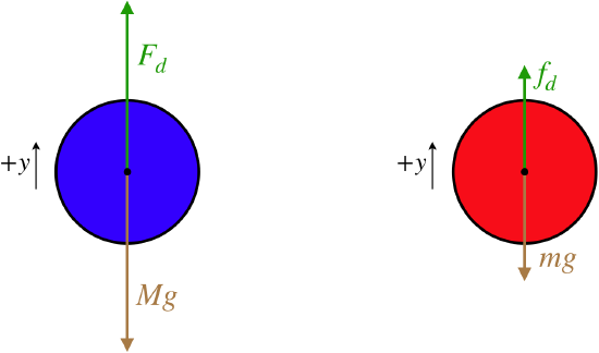
A sign hangs from a wire that is attached to a ring that is also attached to two wires (one of which is horizontally-oriented), as shown in the diagram. The wires and ring have negligible mass.
- Analysis
-
Clearly the sign is being held motionless due to the tension force in the wire attached to it canceling-out the gravity force on it. As obvious as this is, we can confirm it with a free-body diagram and Newton's second law, since we know that the sign is not accelerating:
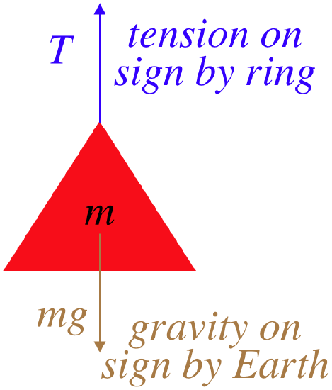
Fnet=+T−mg=ma=0⇒T=mg
It is unlikely that this will be all that the problem is about, however, as it doesn't say anything about the other two wires or the angle θ. Clearly the FBD of the sign will not help us with those, so we turn to a FBD of the ring:
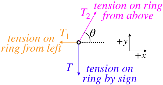
We see that now the force vectors are in two dimensions, which means we will have two equations that come from Newton's second law – one for each component of the net force. As we noted for the sign previously, the system remains at rest, which means that the acceleration vector is zero (and therefore both of its components are as well). Only the tension force T2 has more than one component, so breaking that up and forming the equations from the second law gives:
Fnet x=−T1+T2cosθ=max=0,Fnet y=−T+T2sinθ=may=0
We can now put together the results of the two FBD's to obtain the tensions T1 and T2 in terms of the weight of the sign, if we note that Newton's third law tells us that the tension on the sign by the ring equals the tension on the ring by the sign (in anticipation of this, we have called both of these forces simply "T" in the free-body diagrams):
T=mg⇒−mg+T2sinθ=0⇒T2=mgsinθ,T1=T2cosθ=mgcotθ
To complete our analysis, we will take a quick look at our final results to see if they make sense. Suppose that the angle θ=90o. Then the sign is essentially hanging straight down from wire #2, and sure enough, the tension force applied by that wire is the entire weight of the sign. Also, in this case, wire #1 should be doing nothing, and indeed T1 comes out to be zero.
Our next example combines several forces and allows for possible acceleration.
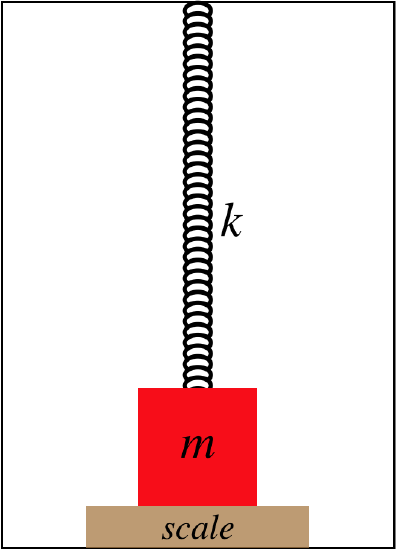
A block is attached to a spring that stretches down from the ceiling of a stationary elevator that is capable of accelerating up or down. The block is then lifted slightly, and a bathroom scale is placed beneath it, so that the block rests on it. The spring is still stretched at this point, but not as fully as when the block was hanging from it.
- Analysis
-
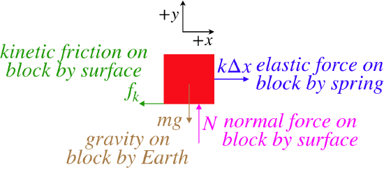
There are several ideas in play here. First, there is a stretched spring, so we will have to include Hooke's law into our analysis. Second, there is a normal force between the block and the bathroom scale. Such scales are constructed to measure weight, but in reality all they can measure is the normal force applied to them. For example, a bathroom scale will give a reading if you put it against a wall and push on it, but that reading is clearly not your weight. And of course there is the gravity force on the block. We start by putting these three forces into a free-body diagram:
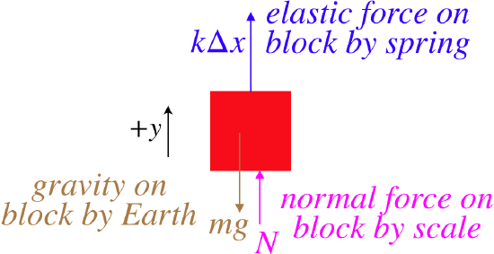
We take our usual next step, which is to apply Newton's second law:
Fnet=+kΔx+N−mg=ma
This is as far as we can take this without more information, but we can imagine what happens if the elevator is accelerating...
If it is accelerating up, then a>0. Clearly the value of mg cannot decrease to allow for the block's acceleration with the elevator, and the spring force cannot increase, because the scale is preventing the spring from stretching any further (and the spring constant can't change, of course). So an upward acceleration can only be accompanied by an increase in the scale's reading (its normal force).
If the elevator is accelerating down, then what can we conclude? Well, either the elastic force or the scale force must decrease (again, mg cannot change). But for the spring force to decrease, the spring must stretch less, which means the block must leave contact with the scale. This would make the normal force zero, that is, as long as the scale is registering any normal force, the spring's amount of stretch is unchanged. So for a very low acceleration, the normal force of the scale will come down, while the spring force remains unchanged, but if the acceleration is larger, then the scale's reading goes to zero, and the mass lifts off the scale, reducing the spring stretch.
Let's get kinetic friction in on the fun...
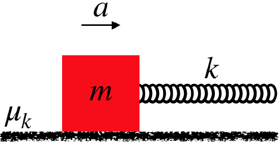
A block is sped-up at a steady rate along a rough, horizontal surface by a stretched spring that pulls on it.
- Analysis
-
Our first observation as we ponder this is that as the block slides, the stretched spring is remaining stretched by the same amount. Presumably whatever is pulling on the other end of the spring must also be accelerating along. We know this because we are told that the acceleration is "at a steady rate". A steady acceleration means a constant net force, so the sum of the horizontal forces must remain constant, and since the friction force remains constant, the spring force must as well. This only occurs if the spring remains stretched the same amount.
Start with a force diagram of the block:
Now apply Newton's second law for both the x and y components, noting that there is no acceleration of the block in the vertical direction:
Fnet x=−fk+kΔx=max,Fnet y=N−mg=may=0⇒N=mg
There is one other piece of information we can add to this analysis. We know something about kinetic friction – it is proportional to the normal force between the two rubbing surfaces. Putting this in the mix and calling the acceleration that only exists along the x-axis simply "a" gives:
fk=μkN=μkmg⇒−μkmg+kΔx=ma
Okay, now let's start re-using themes, but include some complications that require a bit more thought. The key to getting through these "trickier" examples is to just "follow the method" – don't try to think too far ahead, or get stuck on a preconceived idea of what you expect to be the answer.
Here is an example in two-dimensions like the hanging sign problem above, but this time our old friend centripetal acceleration from Chapter 1 is included.
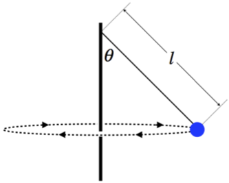
A tetherball swings around a pole, making a full circle at regular time intervals. The rope has negligible mass.
- Analysis
-
Start with a force diagram of the ball, including a coordinate system (we will dispense with the rather obvious force phrase descriptions here):
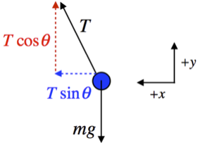
Next sum the forces along the x and y axes and apply Newton's second law:
Fnet x=Tsinθ=max,Fnet y=Tcosθ−mg=may
The ball is not accelerating vertically, as it remains at the same constant height, so ay=0. In the horizontal direction, however, the motion of the ball is changing direction, which means that it must be accelerating. This motion is circular, so the acceleration is toward the center of the circle, and if the ball is moving at a speed v, this centripetal acceleration is:
ax=v2R
where R is the radius of the circle. Putting these two accelerations in above gives:
Tsinθ=mv2R,Tcosθ−mg=0
The tension T can be eliminated from these equations (and the value of the mass m also cancels-out) to give:
tanθ=v2gR
We can take it even a little further than this. The description mentions "regular time intervals" for the tetherball's motion. If we call the interval for a full revolution "t", then we can relate the speed v to the radius of the circle and the time interval:
v=circumferencet=2πRt⇒tanθ=4π2Rgt2
We can even take one more step. In the diagram given, the length of the rope is labeled as "l". The radius of the circle can easily be written in terms of this length and the angle θ, giving us a final result that relates the interval to the angle and length of rope:
R=lsinθ⇒cosθ=gt24π2l
Another situation where kinetic friction comes into play, though it is a tough one to rely upon intuition for – just follow the method!
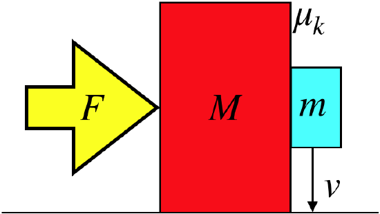
A large block is pushed along a horizontal, frictionless surface by an external fixed force. In contact with the rear vertical face of the large block is a smaller block, and as the two blocks are accelerated horizontally, the smaller block slides down the rough (not frictionless) face of the larger block at a constant speed.
- Analysis
-
Few problems demonstrate the importance of drawing free-body diagrams better than this one. One thing that is interesting here is that we have several choices for what is the "object" in the free-body diagram. We can choose the large block, the small block or the system of both blocks. As this is just analysis, and we don't know where we will eventually need to go, we'll just do all three:
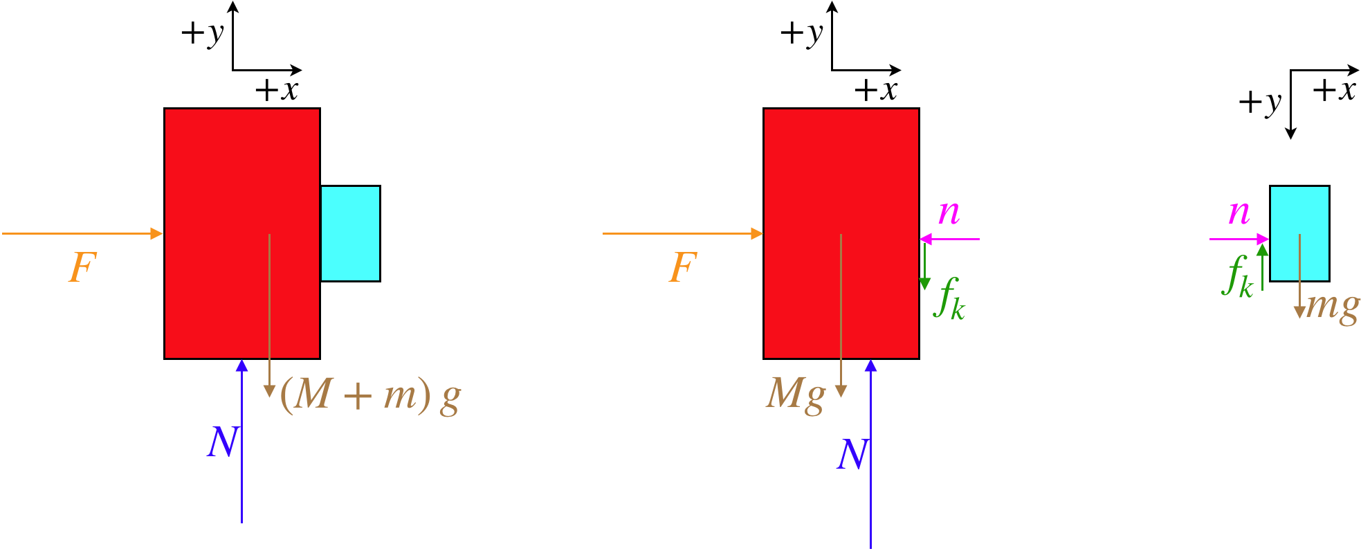
These show nicely how the two third-law pair forces (the normal force between the blocks and the kinetic friction force between the blocks) appear when we split the blocks into separate systems, but are unneeded when they are internal to the system of two blocks. Next let's write down the equations that come from Newton's second law for each of these diagrams:
two blocks
Fnet x=F=(M+m)ax,Fnet y=N−(M+m)g=may
large block
Fnet x=F−n=Max,Fnet y=N−Mg−fk=may=0
small block
Fnet x=n=max,Fnet y=mg−fk=may
Next we need to consider the accelerations. The acceleration of the big block in the vertical direction is clearly zero, as it never moves up or down. The values for the ay's in the two block and small block cases are not as obvious, as the center of mass of each of these system is clearly falling. But we are given that the descent of the small block is at a constant speed, so while the center of mass is moving in the −y direction, it is not accelerating in either case. We can therefore declare that both of the ay's appearing in the equations above are zero. The acceleration in the +x-direction is obviously not zero, but whatever it is, with the blocks both moving together, it is the same for all three systems. We therefore can compute the acceleration for all three systems most easily from the two-block system:
a=FM+m
Anything else we can extract from what we are given? Well, from the small block system, given that the vertical acceleration is zero, we know that the kinetic friction force equals the block's weight, but we can also write the kinetic friction force in terms of the coefficient of kinetic friction and the normal force between the surfaces:
mg−fk=may=0⇒mg=fk=μkn
We know the horizontal acceleration of the small block, and the only horizontal force on it is n, so we can plug in for n to finally get:
mg=μkn=μkma=μkmFM+m⇒F=1μk(M+m)g
This tells us that the force that needs to be applied to allow the block to slide at a constant speed is greater than the weight of the two-block system by a factor of μ−1k (recall that coefficients of kinetic friction are generally less than 1). If the force is any greater than this, then the normal force between the blocks will be greater, making the friction force greater than the weight of the small block, and the small block's decent will actually slow. If the force is less than this amount, the friction force will be less than the weight of the small block, and its descent will speed up.
Here's an example to make sure you haven't forgotten about the role of center of mass in Newton's laws.
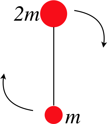
A system of two balls of different masses attached by a string are thrown horizontally through the air, and rotates at a steady rate about its center of mass as it goes. Air resistance is negligible for the system, and at the moment the balls are thrown, the larger ball is directly above the smaller ball, as in the diagram.
- Analysis
-
Let's start with a free-body diagram of the system. As it is flying through the air, there is only one force on it – gravity. The internal tension forces between the balls are a third law pair, and can therefore be ignored. At some arbitrary moment during the flight, the FBD looks like:
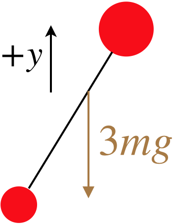
Note that we strive to locate the total gravity force on the system at the center of mass for the system, and if we treat the two balls as though they are particles, the center of mass comes out to be two-thirds of the distance from the smaller mass m to the larger mass 2m.
What is interesting here is that with this being the only force, the acceleration of this system is simple to compute:
Fnet y=−3mg=3may,ay=−g
In other words, this object is just a standard projectile! As such, we can use the projectile equations to describe its motion. But we have to be careful – this only describes the motion of the center of mass of the system, not the individual balls at the ends of the string. But if we know something about the rate of rotation of the two balls, then if we are given a time, we can use the projectile equations to locate the center of mass, and the rotation rate to locate the balls relative to that center of mass.
And finally, an example that combines understanding of graphs with Newton's laws.
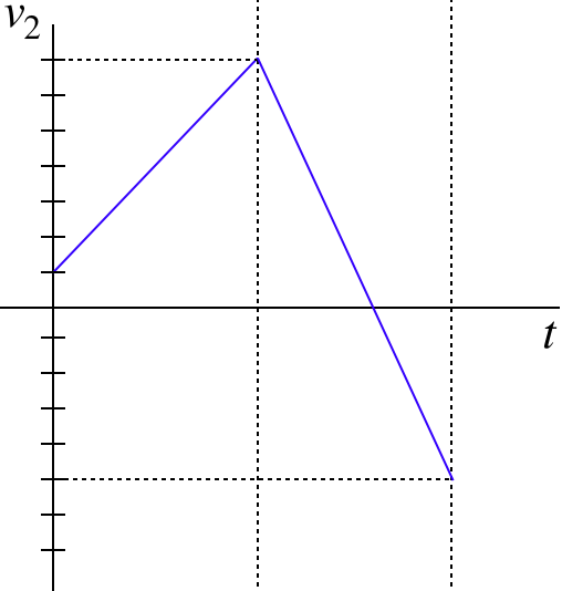
Two particles, #1 and #2 interact only with each other. The acceleration of particle #1 is plotted on the graph below for a period of time. The velocity of particle #2 was plotted simultaneously, but the data for the second half of the time interval was lost, and its graph is also shown below.
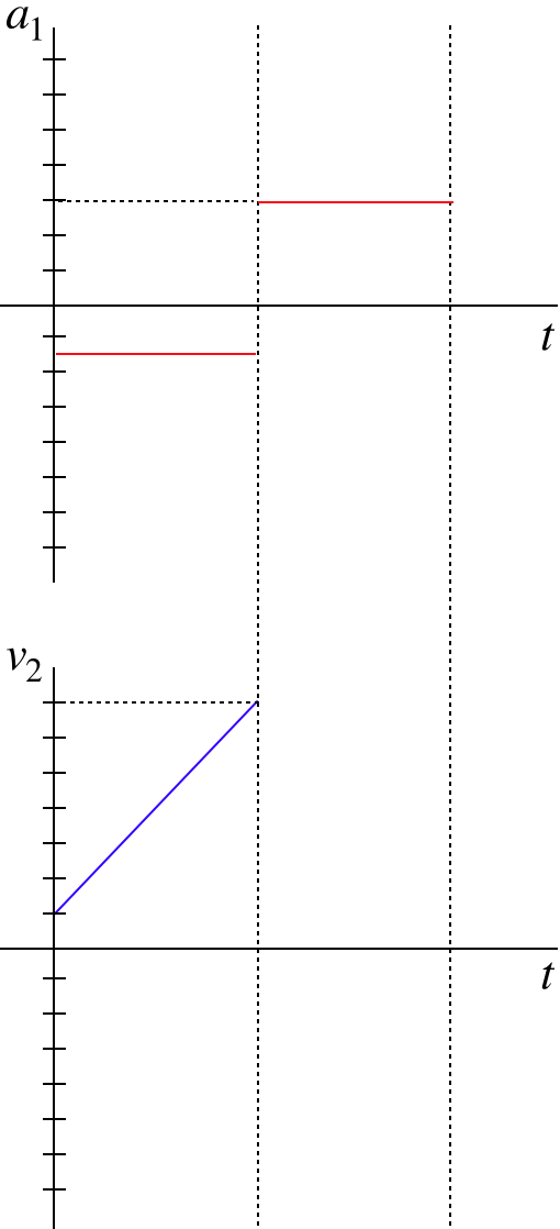
- Analysis
-
This is one of those rare occasions when a free-body diagram is not called for, but Newton's laws are still very important to the analysis. We are given that these two graphs are for the motions of particles that only interact with each other. Given that these graphs represent accelerated motion, it must be that the particles exert forces on each other. From Newton's third law, these forces must be equal-and opposite.
We cannot extract the forces from these plots, we can only get the accelerations. But by Newton's second law, these are proportional to the forces. The acceleration of particle #1 can be read directly from the graph, and it is −1.5units for the first half. Particle #2's acceleration is the slope of its velocity graph, and that is +6.0units for the first half. With 4 times as much acceleration and an equal force on it, we conclude that particle #2 has one fourth the mass of particle #1.
The masses of the particles do not change for the second half of the time interval, so since we know the acceleration of particle #1 +3units, we also immediately know the acceleration of particle #2 from Newtons's second and third laws – it must be −4 times particle #1's acceleration, or −12units. If we are asked to add the second half of the time interval to particle #2's velocity graph, it would have to be a straight line that drops 12 units during that second interval: