
4.1: Images


- Last updated
- Dec 29, 2023
- Save as PDF

( \newcommand{\kernel}{\mathrm{null}\,}\)
Using Rays to Locate Light Sources
In our discussion leading to the law of reflection, we found (Figure 3.6.6) that if we view the light from a point source after it is reflected off a plane, then the spherical wave we see appears to originate not from the point source, but from another point behind the reflecting plane. We will now look more generally at locating this apparent origin of a source of light (which we have dubbed "image"). We are through with doing the hard work of analyzing optical systems with Huygens's principle and wave propagation, however. Instead, we will now embrace the tool of rays, keeping in mind as we do the fact that rays do not represent what is actually happening with light – they just make it easier to do the geometry of linking actual light sources with the images observed. This approach to the study of certain aspects of light is therefore generally referred to as geometrical optics.
Alert
This point cannot be emphasized enough: We will sketch rays so that we can do geometry, but these are just imaginary lines that we use for our own purposes to simplify our work – they do not represent actual light, and in many cases we will see, there isn't any light at all where we have drawn the ray!
Up to now, we have discussed only plane waves and point sources of light, but when we look at something, we receive light from every part of it that is visible to us. That is, there are actually several point sources of light. For the purpose of simplifying our analysis, we will reduce the objects we look at to their bare essence, but they must be more nuanced than merely a single point. At the very least, we would like to have some measure of the size and orientation of what we are looking at. As we will see, the path that light takes from the object to our eye can alter not only the location of the apparent source of the light, but also what we perceive to be its size and orientation.
The simplest way to exhibit the two attributes of size and orientation is with an arrow. The directionality of the arrow gives us a sense of orientation, and the length of the arrow a measure of its size. If the object arrow points upward, then depending upon what happens to the light in transit from the object to the observer, the image arrow will either point upward as well (it is upright, or erect), or it will reverse direction and point downward (inverted). When we compare the lengths of the object and image arrows, the image arrow is laterally magnified if it is longer than the object arrow, and laterally diminished if it is shorter. Doing this reduces our analysis to using rays and geometry to determine where the base and point of the image arrow are located.
Rays radiate outward from a point source (such as the point of the image arrow). If we draw a single ray that enters our eye, we only know the direction from which the light has come, not how far away it is. The way that we locate the source of the light is to view another ray. This allows us to backtrack the rays to see where they intersect.
Figure 4.1.1 – Finding an Image
To get the full arrow image, this process would need to be followed for both the pointed end and the base. When looking directly at an object, following this process locates the image exactly where the object is located. The image location (where we see the light coming from) is the same as the object location (where the light is actually coming from), the size of the image is the same as the size of the object, and the image is the same orientation as the object. This is all so boring! What interests us is when the image data differs from the object data, and this can only be accomplished when the light reaches our eyes in a less direct manner. Then when we backtrack the rays they will converge at a different place than the source from which they actually originated.
Plane Reflector
We used a clever symmetry argument with Huygens's principle in Section 3.6 to find the image of a point source of light in the presence of a plane reflector. We'll now repeat this conclusion with the ray method, using the law of reflection and basic geometry. We start by drawing the object, and selecting a ray that comes out of it, reflects, and enters an eye.
Figure 4.1.2 – Plane Reflector: First Ray

The law of reflection assures us that the angle that the ray coming from the object makes with the perpendicular to the plane is the same as the angle the ray coming into the eye makes. We'll use this fact in a moment, but first we need to pick another ray. To get the answer we can pick any ray we like, but as using these rays is merely our trick for finding the image, we might as well make the geometry we have to do as easy on ourselves as possible. Let's choose as our second ray the one that strikes the reflector perpendicularly, and comes straight back (we can place the eye directly behind the tip of the arrow).
Figure 4.1.3 – Plane Reflector: Two Intersecting Rays
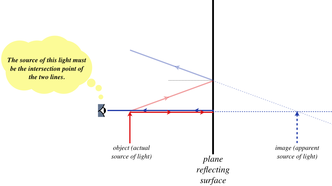
Okay, now for the geometry. Thanks to the law of reflection, we can see that the angle the first (blue) image ray makes with the horizontal is the same as the angle that the first (red) object ray makes with the horizontal. The two right triangles formed by rays on the opposite sides of the reflector are therefore similar, and since they share a side, they are congruent. The image is therefore the same distance to the right of the reflector as the object is to the left of it. If we repeat this process for the base of the arrow, we get the same result, and with the object and image bases and tips directly across from each other, the image is clearly the same size as the object (neither magnified nor diminished), and the image is upright (the same orientation as the object).
As simple as this example is, it shows clearly a case where the apparent source of light (i.e. the image) is disconnected from the actual source of light. No matter how complicated the geometry might get, the method of finding the image is the same – determine the position that the observer backtracks two (or more) rays to.
Alert
One last warning, then you are on your own... It is easy to get caught up in the process of finding the image (backtrack rays, do geometry, etc.), but this process is not tracking any actual physical process – the light is not traveling in rays, and in fact there is not even any light where we have drawn image rays to the right of the reflector! Using rays is just a trick that makes our lives easier. For this plane refractor, what is actually physically happening to the light is better depicted by Figure 3.6.5.
Sign Conventions
Not all examples in geometrical optics are as easy to do geometrically as the plane reflector, so it is helpful to develop some mathematical definitions, formulas, and conventions that can be used for all cases. We'll begin the process of making such definitions here, and will continue to add to them as the number of situations we can cover grows. In particular, in order for mathematical formulas to work out properly, we will need to define when a variable is positive or negative. These are referred to as sign conventions, and at times these can be quite confusing. This is because – at least at first – the conventions will seem overly complicated or cryptic. This is necessary, because making definitions that are too simple forces us to make new definitions later for more complicated situations, and we want to avoid this.
For the plane refractor (and in fact for every optical device we will examine), there is one critical region along the horizontal axis. For the case above, it is the plane at which the reflection occurs. We choose this important boundary to be an "origin" of sorts, from which distances are measured. We start with the following variable definitions and their associated sign conventions:
namesymbolpositive whennegative whenobjectdistancesobjectonincomingsideobjectonothersideimagedistances′imageonoutgoingsideimageonotherside
Okay a clarification is in order here. "Incoming" and "outgoing" refer to the direction of the rays relative to the origin – rays pointing toward the reflector (or more generally, the "origin") are on the "incoming" side, and rays pointing away from it are on the outgoing side. While "incoming" and "outgoing" sound like opposites, they are not. This is very clear for the case of the reflector, where the incoming and outgoing sides are the same (the rays come in from the left, and go back out to the left). But in other cases we will examine, the rays will pass through the "origin," making the incoming and outgoing sides different.
For the plane reflector, we found that the magnitudes of the object and image distances are equal, but what about the signs? Well, the light is coming into the reflector from the left, and the object is on the left, so it is on the incoming side, which means that s>0. The light is going away from the mirror on the left side, so it is the outgoing side, and the image is located on the other side, so s′<0. We therefore conclude, for the plane reflector:
We will see many more sign conventions, and we'll add them to the list as they come up.
Plane Refractor
Obviously any way that we can get the rays representing the light to change direction will lead to a case where the image position does not coincide with the object position. Reflection is one way to make this happen, and another way is refraction. We will therefore examine the simplest case of a refraction-induced image – the plane refractor. This consists of two regions with different indices of refraction, delineated by a plane boundary, such as looking at an object below the surface of a pool of still water.
The light coming from the object (which we will say is in a medium with index of refraction n1) will bend as it crosses the boundary into a new medium, where the observer resides, with index of refraction n2, according to Snell's law (Equation 3.6.4). In this case, the plane boundary between the two media is the "origin" from which we measure everything.
Now proceed as we did for the reflector: Start with an arbitrary ray that comes from the object, passes through the boundary, and enters the eye of an observer. For the sake of drawing a figure, we will look at the case that the index of refraction of the medium where the object resides is greater than the index of refraction of the medium of the observer.
Figure 4.1.4 – Plane Refractor: First Ray
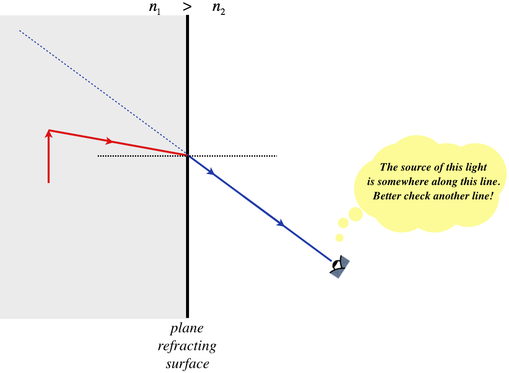
We need another ray to find the intersection point that defines the position of the image, and once again we will make things easy on ourselves by choosing the ray that strikes the refracting plane perpendicularly. This ray passes straight through without bending, making the location of the intersection point quite simple.
Figure 4.1.5 – Plane Refractor: Two Intersecting Rays
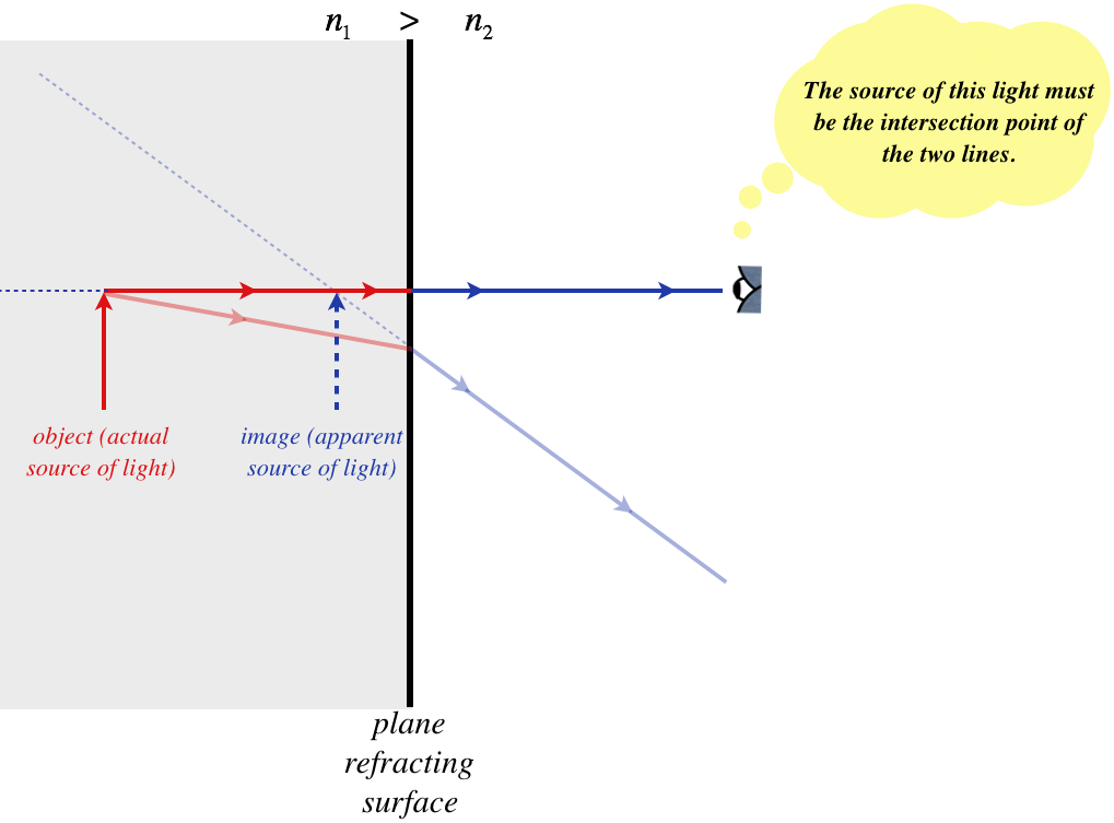
Before we go on to do the math associated with the geometry, there is one important thing to point out here. Unlike the plane reflector case, where we could show using Huygens's principle that all of the rays that emerge backtrack to the same point, it is far from clear that this must be true in this case. In fact it isn't true! That is, if we carefully keep drawing rays for other angles, the angled rays will intersect the direct (un-deflected) ray at different points. This is not difficult to prove: There is some point on the surface for which a ray from the object is totally internally reflected. Light rays coming out of the object at angles greater than this never escape the medium, so they cannot be viewed by the observer, so they cannot be backtracked to the same image as any other rays.
Despite this "problem," we can nevertheless get a useful approximate result. If we assume that the object is viewed from angles not too far off a direct viewing (i.e. small refracted angles), then the image's position can be determined to a close approximation. Under this approximation, we'll first assert the following, which will be useful shortly:
for a small angle θ:sinθ≈tanθ
Now let's label some values from the figure above. Namely, we'll define the incoming angle θ1, the refracted angle θ2, the height of the above the axis h, the object distance s, and the image distance s′ (note we have already defined the two indices of refraction):
Figure 4.1.6 – Geometry of the Plane Refractor
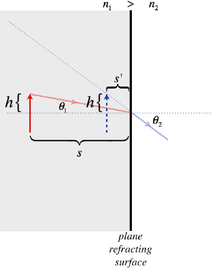
Start by constructing the tangents of the two angles:
tanθ1=hstanθ2=hs′
Now apply the small angle approximation to turn these tangents into sines, and apply Snell's law:
hs≈sinθ1hs′≈sinθ2n1sinθ1=n2sinθ2}s′=n2n1s
So just as for the plane reflector where we found the relationship between the object and image distance (Equation 4.1.2), we have done the same for the plane reflector. Let's check to see if the sign conventions work out properly for this equation. The object is to the left of the refracting plane, and the light reaches the refracting plane from the left, so the object is on the incoming side, which means that s>0. The light is leaving the refracting plane going to the right (to the observer), so the right hand side is the outgoing side. The image is on the left, so it is on the side "other than" the outgoing side. Therefore the image distance is actually negative. Indices of refraction are always positive, so we need a minus sign to make the formula correct with our sign conventions:
plane refractor:s′=−n2n1s