First Law of Thermodynamics
The First Law of Thermodynamics is our Energy-Interaction Model applied to systems where only the internal energies are changing. The 1st law states that: the change in internal energy is equal to the energy added or removed as heat and/or work. Symbolically, using U to refer to internal energy, the 1st Law is given by a familiar equation:
\[ \Delta U = Q + W \]
where, generally, ∆U = ∆Ebond + ∆Ethermal + ∆Eatomic + ∆Enuclear and is called the change in internal energy. Atomic and nuclear energies includes changes in the atomic states of atoms that are not involved in chemical bonds. In normal chemical reactions and phase changes, there are no changes in atomic or nuclear energies, so the last two terms are zero for the types of physical systems we study in this course. This equation is always true as long as we interpret \(\Delta U\) to include all changes of energy associated with the physical system, and we mean by \(Q\) and \(W\) the addition of energy as heat or as work to the system when Q and/or W are positive or a removal of energy from the system as heat or as work when Q and/or W are negative.
Thermodynamic State
One aspect of thermodynamics that we will study is the evolution of systems from one state to another. To understand this we need to be able to describe the initial and final states, known as a thermodynamic states, and to describe the process for getting from one to the other. In describing individual states, we can use certain variables that have unique values for that thermodynamic state. These variables are called state variables. For example, an ideal gas in a particular state is described by state variables pressure, P, volume, V, temperature, T, and internal energy, U. State variables do not depend on the process or how the system evolved to that state. Work, W, and heat, Q, are not state variables, since they depend on the process between two states. As a system changes, due to heat or work being added or removed, the values of these state variables will change. When we discuss how one state variable depends on other state variables, we can refer to that state variable as a state function. Relationships between these variables are expressed in equations of state. For example, in the previous section we introduced one equation of state – the ideal gas equation, \(PV = nRT\).
State Diagrams
Previously we used Energy-Interaction diagrams as a useful representational tool for analyzing energy conservation for specific phenomenon. To describe changes in state variables as a system undergoes change, we can use a different representational tool: state diagrams. A state diagram is a graph of one state variable plotted as a function of another state variable for a particular process. Because it is frequently the case that two state variables completely determine the state of the system, a two dimensional state diagram can be a very useful and sufficient representational tool.
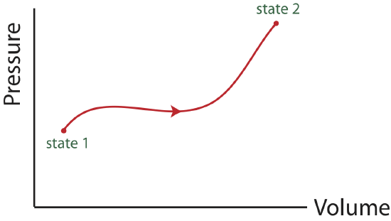
Often, the pressure, P, and volume, V, are chosen to be the two representative state variables in a state diagram. Another useful pair is entropy and temperature, that will be introduced later in this chapter. One reason the two-variable state diagram is such a useful representation, is because it is possible to easily follow the path a system takes as it undergoes the process from some initial to some final state. By path, we mean the continuous line of intermediate states that a system passes through, as it moves from an initial to a final state. The PV diagram below shows one of the infinite number of possible paths connecting state 1 with state 2.
Figure 4.4.1: PV state diagram.

A PV diagram needs to contain information about:
- initial and final states.
- the path connecting initial and final states.
- the direction of the path.
We will find many uses for PV diagrams, especially for understanding the energy exchanges that take place as thermodynamic systems undergo a change. One of the most important things we have already seen is that the area under a PV-curve represents the work done on or by the system during a volume change. This work, in turn, is directly related to heat transfer and changes in the internal energy of the system.
It makes no sense to try to represent a state of a system on state diagram, unless the system is in equilibrium. The state variables, which are macroscopic variables, must have unique values that are the same throughout the system, which can only be measured once the system is in equilibrium. Likewise, it makes no sense to talk about a particular path along a state diagram unless all the intermediate states are equilibrium states as well. This is not to say that a real physical system cannot go from one state, say state 1 in the example above to state 2 and not follow a set of intermediate states that are equilibrium states. In fact, most processes do not follow a path that continuously moves along a set of equilibrium states. It is just that we cannot show the path if it does not pass through a series of equilibrium states. The end points, however, are well defined, regardless of how the system gets from the initial to the final equilibrium state. The system can start in an equilibrium state and end up in an equilibrium state and never be in an equilibrium state along the way.
Types of Problems
There are typically three quantities for a particular process that we can calculate from a PV diagram alone:
- \(W\): work can be obtained directly from the PV diagram by either doing an integral or calculating an area under a curve. The sign of work can be found by considering the direction of the process indicated on the PV diagram. From definition of work in Equation 4.2.6, if the volume increased during a process work is negative, if the volume decreases work is positive, and if the volume stays constant work is zero.
- \(\Delta U\): when there is no change in bond energy, change in internal energy is equal to the change in thermal energy, which can be calculated using \(\Delta E_{th}=\dfrac{1}{2}(\text{total \# modes})k_B\Delta T\). Initial and final temperatures can be calculated from the PV diagram using the Ideal Gas Law: \(PV=nRT\). Also, information about the total number of particles and the type of gas is needed in order to calculate the total number of modes.
- \(Q\): the heat entering or leaving the system can be found indirectly from the PV diagram by calculating \(W\) and \(\Delta U\) first as described in 1. and 2., and then using the 1st Law of Thermodynamics: \(Q=\Delta U-W\).
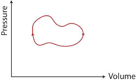
There is a special type of process known as a thermodynamic cycle, which returns a system to its original state. An example of a PV diagram for a cycle is shown in the figure below.
Figure 4.4.2: A thermodynamic cycle.

For a cycle:
- \(W\): when the cycle is clockwise work is negative, and when its counterclockwise work is positive.
- \(\Delta U\): the internal energy is a state variable, thus, it is path independent. Since the system returns to its original state, there is no change in internal energy.
- \(Q\): since the change in internal energy is zero for a cycle, \(Q=-W\).
Example \(\PageIndex{1}\)
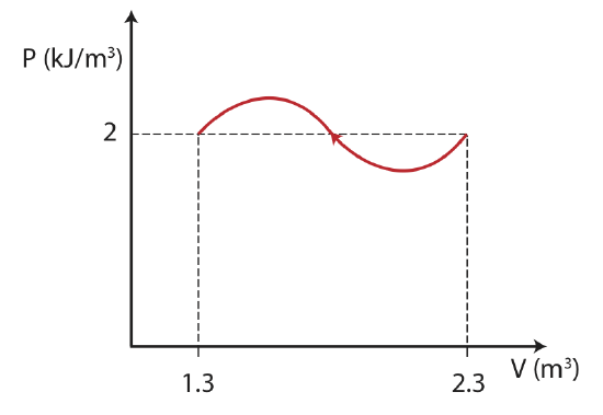
The thermodynamic process below is described by a PV diagram for 1 mole of an ideal monatomic gas that does not change phase. During this process, 5kJ of heat is removed from the system.

a) Calculate the final temperature of the gas.
b) What is the change in internal energy for the process?
c) Calculate the work in the process. Is the work being done by the system or on the system?
- Solution
-
a) Here will use the Ideal gas law and solve for the final temperature:
\[T_f=\dfrac{PV}{nR}=\dfrac{(2\times 10^3 J/m^3)(1.3 m^3)}{(1 mole)(8.314 J/Kmol)}=312.7 K \nonumber \]
b) Since the system does not undergo a phase change, the change in internal energy is equal to the change in thermal energy. The change in thermal energy is:
\[\Delta E_{th}=\dfrac{1}{2}(\text{total \# modes})k_B\Delta T\nonumber \]
To find \(\Delta T\), we need to find the initial temperature as well:
\[T_i=\dfrac{PV}{nR}=\dfrac{(2\times 10^3 J/m^3)(2.3 m^3)}{(1 mole)(8.314 J/Kmol)}=553 K \nonumber \]
For one mole of a monatomic gas: \(\text{total \# modes}=(1 N_A)(3 \text{modes/particle})=3N_A\). Using \(R=k_BN_A\) we get:
\[\Delta E_{th}=\dfrac{1}{2}(3)(8.314 J/Kmol)(312.7 K-553 K)=-3 KJ\nonumber \]
c) Using 1st law:
\[W=\Delta U-Q=-3KJ+5kJ=2kJ\nonumber\]
The positive work obtained from the calculation above tells us that work is being done on the system. We can also see this directly from the diagram, since the volume is decreasing in this process work is positive.
Example \(\PageIndex{2}\)
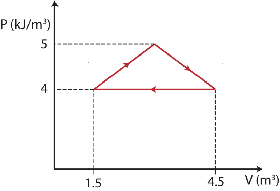
The thermodynamic cycle below (making a shape of an isosceles triangle) is described by a PV diagram for 1 mole of an ideal monatomic gas that does not change phase.


Find the total change in internal energy, the work done, and the heat for this thermodynamics cycle.
- Solution
-
In a cycle the start and end states are the same, thus there is no change in the values of state variables. Since \(\Delta T=0\), the total change in internal energy is zero as well, \(\Delta U =0\). This simplifies the 1st law to
\[W=-Q\nonumber\]
The sign of work is negative since the cycle is clockwise. We can find work by finding the area inside the cycle:
\[W=-\dfrac{1}{2}(1\times 10^3 J/m^3)(4.5m^3-1.5m^3)=-1.5 kJ\nonumber\]
Therefore, the heat added is 1.5 kJ.


