Physics LibreTexts

8.7: Circuit Problem Solving

  • Page ID
    104123
  • \( \newcommand{\vecs}[1]{\overset { \scriptstyle \rightharpoonup} {\mathbf{#1}} } \)

    \( \newcommand{\vecd}[1]{\overset{-\!-\!\rightharpoonup}{\vphantom{a}\smash {#1}}} \)

    \( \newcommand{\id}{\mathrm{id}}\) \( \newcommand{\Span}{\mathrm{span}}\)

    ( \newcommand{\kernel}{\mathrm{null}\,}\) \( \newcommand{\range}{\mathrm{range}\,}\)

    \( \newcommand{\RealPart}{\mathrm{Re}}\) \( \newcommand{\ImaginaryPart}{\mathrm{Im}}\)

    \( \newcommand{\Argument}{\mathrm{Arg}}\) \( \newcommand{\norm}[1]{\| #1 \|}\)

    \( \newcommand{\inner}[2]{\langle #1, #2 \rangle}\)

    \( \newcommand{\Span}{\mathrm{span}}\)

    \( \newcommand{\id}{\mathrm{id}}\)

    \( \newcommand{\Span}{\mathrm{span}}\)

    \( \newcommand{\kernel}{\mathrm{null}\,}\)

    \( \newcommand{\range}{\mathrm{range}\,}\)

    \( \newcommand{\RealPart}{\mathrm{Re}}\)

    \( \newcommand{\ImaginaryPart}{\mathrm{Im}}\)

    \( \newcommand{\Argument}{\mathrm{Arg}}\)

    \( \newcommand{\norm}[1]{\| #1 \|}\)

    \( \newcommand{\inner}[2]{\langle #1, #2 \rangle}\)

    \( \newcommand{\Span}{\mathrm{span}}\) \( \newcommand{\AA}{\unicode[.8,0]{x212B}}\)

    \( \newcommand{\vectorA}[1]{\vec{#1}}      % arrow\)

    \( \newcommand{\vectorAt}[1]{\vec{\text{#1}}}      % arrow\)

    \( \newcommand{\vectorB}[1]{\overset { \scriptstyle \rightharpoonup} {\mathbf{#1}} } \)

    \( \newcommand{\vectorC}[1]{\textbf{#1}} \)

    \( \newcommand{\vectorD}[1]{\overrightarrow{#1}} \)

    \( \newcommand{\vectorDt}[1]{\overrightarrow{\text{#1}}} \)

    \( \newcommand{\vectE}[1]{\overset{-\!-\!\rightharpoonup}{\vphantom{a}\smash{\mathbf {#1}}}} \)

    \( \newcommand{\vecs}[1]{\overset { \scriptstyle \rightharpoonup} {\mathbf{#1}} } \)

    \( \newcommand{\vecd}[1]{\overset{-\!-\!\rightharpoonup}{\vphantom{a}\smash {#1}}} \)

    \(\newcommand{\avec}{\mathbf a}\) \(\newcommand{\bvec}{\mathbf b}\) \(\newcommand{\cvec}{\mathbf c}\) \(\newcommand{\dvec}{\mathbf d}\) \(\newcommand{\dtil}{\widetilde{\mathbf d}}\) \(\newcommand{\evec}{\mathbf e}\) \(\newcommand{\fvec}{\mathbf f}\) \(\newcommand{\nvec}{\mathbf n}\) \(\newcommand{\pvec}{\mathbf p}\) \(\newcommand{\qvec}{\mathbf q}\) \(\newcommand{\svec}{\mathbf s}\) \(\newcommand{\tvec}{\mathbf t}\) \(\newcommand{\uvec}{\mathbf u}\) \(\newcommand{\vvec}{\mathbf v}\) \(\newcommand{\wvec}{\mathbf w}\) \(\newcommand{\xvec}{\mathbf x}\) \(\newcommand{\yvec}{\mathbf y}\) \(\newcommand{\zvec}{\mathbf z}\) \(\newcommand{\rvec}{\mathbf r}\) \(\newcommand{\mvec}{\mathbf m}\) \(\newcommand{\zerovec}{\mathbf 0}\) \(\newcommand{\onevec}{\mathbf 1}\) \(\newcommand{\real}{\mathbb R}\) \(\newcommand{\twovec}[2]{\left[\begin{array}{r}#1 \\ #2 \end{array}\right]}\) \(\newcommand{\ctwovec}[2]{\left[\begin{array}{c}#1 \\ #2 \end{array}\right]}\) \(\newcommand{\threevec}[3]{\left[\begin{array}{r}#1 \\ #2 \\ #3 \end{array}\right]}\) \(\newcommand{\cthreevec}[3]{\left[\begin{array}{c}#1 \\ #2 \\ #3 \end{array}\right]}\) \(\newcommand{\fourvec}[4]{\left[\begin{array}{r}#1 \\ #2 \\ #3 \\ #4 \end{array}\right]}\) \(\newcommand{\cfourvec}[4]{\left[\begin{array}{c}#1 \\ #2 \\ #3 \\ #4 \end{array}\right]}\) \(\newcommand{\fivevec}[5]{\left[\begin{array}{r}#1 \\ #2 \\ #3 \\ #4 \\ #5 \\ \end{array}\right]}\) \(\newcommand{\cfivevec}[5]{\left[\begin{array}{c}#1 \\ #2 \\ #3 \\ #4 \\ #5 \\ \end{array}\right]}\) \(\newcommand{\mattwo}[4]{\left[\begin{array}{rr}#1 \amp #2 \\ #3 \amp #4 \\ \end{array}\right]}\) \(\newcommand{\laspan}[1]{\text{Span}\{#1\}}\) \(\newcommand{\bcal}{\cal B}\) \(\newcommand{\ccal}{\cal C}\) \(\newcommand{\scal}{\cal S}\) \(\newcommand{\wcal}{\cal W}\) \(\newcommand{\ecal}{\cal E}\) \(\newcommand{\coords}[2]{\left\{#1\right\}_{#2}}\) \(\newcommand{\gray}[1]{\color{gray}{#1}}\) \(\newcommand{\lgray}[1]{\color{lightgray}{#1}}\) \(\newcommand{\rank}{\operatorname{rank}}\) \(\newcommand{\row}{\text{Row}}\) \(\newcommand{\col}{\text{Col}}\) \(\renewcommand{\row}{\text{Row}}\) \(\newcommand{\nul}{\text{Nul}}\) \(\newcommand{\var}{\text{Var}}\) \(\newcommand{\corr}{\text{corr}}\) \(\newcommand{\len}[1]{\left|#1\right|}\) \(\newcommand{\bbar}{\overline{\bvec}}\) \(\newcommand{\bhat}{\widehat{\bvec}}\) \(\newcommand{\bperp}{\bvec^\perp}\) \(\newcommand{\xhat}{\widehat{\xvec}}\) \(\newcommand{\vhat}{\widehat{\vvec}}\) \(\newcommand{\uhat}{\widehat{\uvec}}\) \(\newcommand{\what}{\widehat{\wvec}}\) \(\newcommand{\Sighat}{\widehat{\Sigma}}\) \(\newcommand{\lt}{<}\) \(\newcommand{\gt}{>}\) \(\newcommand{\amp}{&}\) \(\definecolor{fillinmathshade}{gray}{0.9}\)

    Solving Electric Circuit Problems

    When tackling a circuit problem you may need to figure out the equivalent resistance of the circuit, voltage drops across resistors, total current coming out of the battery or current through specific resistors, power dissipated by resistors or provided by the battery, relative brightness of light bulbs in a circuit, the effect of a shorted resistor, or a burnt one, and more.

    Below are a few useful steps to follow. Even though these basics steps are provided, it is never a good idea to follow a procedure verbatim. This procedure is a good starting guide of tacking some circuit problems, but might not apply to all of them in the order provided. As you start working with more advanced scenarios, think of ways of how you can work backwards, follow the steps in different order, or only use some of the steps to solve your particular problem most efficiently.

    Circuit problem solving procedure:

    1) Calculate the equivalent resistance of the circuit. First combine all the series resistors and then calculate the parallel ones. Use  the following equations:       

     \[\text{series}:~~R_{eq}=\sum_i^n R_i\] 

    \[\text{parallel}:~~\dfrac{1}{R_{eq}}=\sum_i^n \dfrac{1}{R_i}\]

    2) Use your result of equivalent resistance to find the total current coming out of the battery:

    \[I_{tot}=\dfrac{\mathcal E}{R_{eq}}\]

    3) Apply the loop rule to all the loops present in the circuit in order to find the relationship between voltage drops and emf of battery. Make sure you are consistent with the direction of the loop you choose. If your loop takes you from a negative to the positive terminal of the battery, you will get, \(+\mathcal E\). If you loop takes you across a resistor in the direction of the current, then the correct sign of the voltage difference should be negative, \(\Delta V=-IR\). In general for any given loop, the following must be true:

    \[\sum \mathcal E+\sum \Delta V =0\]

    4) Apply the junction rule at all the junctions to find the relationship between the current going into the junction and the individual currents in each of n paths:

    \[I_{in}=\sum_i^n I_i\]


    Example \(\PageIndex{1}\)

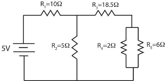
    For the circuit show below find the current and voltage for each of the five resistors.

    electric-circuit-example.png

     
    Solution

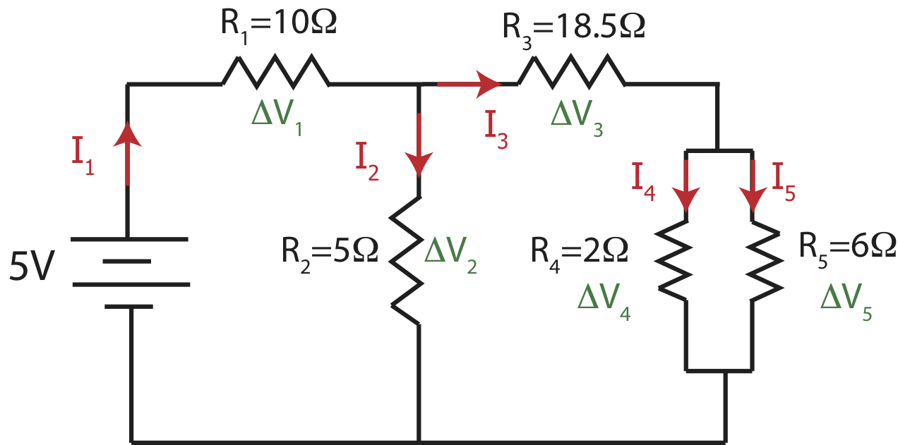
    It is a good idea to start by labeling all the currents and voltage as shown below.

    electric-circuit-example-S1.png


    Since all the resistances are known, the first natural step is to find the equivalent resistance. For this particular circuit the best way to combine resistors is: resistors 4 and 5 are in parallel, their combination \(R_{45}\) is in series with \(R_3\). The combination of 3,4, and 5, \(R_{345}\) is in parallel with 2, and their combination, \(R_{2345}\) is in series with \(R_1\).

    First, calculating \(R_4\) and \(R_5\) in parallel:

    \(\dfrac{1}{R_{45}}=\dfrac{1}{R_4}+\dfrac{1}{R_5}=\dfrac{1}{2\Omega}+\dfrac{1}{6\Omega}=\dfrac{2}{3\Omega}\)

    \(R_{45}=\dfrac{3}{2}\Omega\)

    Combining \(R_3\) in series with \(R_{45}\):

    \(R_{345}=R_3+R_{45}=18.5\Omega+1.5\Omega=20\Omega\)

    Combining \(R_3\) in parallel with \(R_{345}\):

    \(\dfrac{1}{R_{2345}}=\dfrac{1}{R_2}+\dfrac{1}{R_{345}}=\dfrac{1}{5\Omega}+\dfrac{1}{20\Omega}=\dfrac{1}{4\Omega}\)

    \(R_{2345}=4\Omega\)

    And finally combining \(R_1\) in series with \(R_{2345}\) to find the equivalent resistance of this circuit:

    \(R_{eq}=R_1+R_{2345}=10\Omega+4\Omega=14\Omega\)

    Resistor 1 is the only resistors which is in series with the battery, so the current through resistor 1, \(I_1\), will be equal to the total current coming out of the battery:

    \(I_1=I_{tot}=\dfrac{\mathcal E}{R_{eq}}=\dfrac{5V}{14\Omega}=0.357 A\)

    Once we know the current through 1, we can find the voltage across resistor 1:

    \(\Delta V_1=-I_1R_1=0.357A\times 10\Omega=-3.57V\)

    Now we can apply the loop rule to the first loop on the left that goes through the battery, resistor 1, and resistor 2 to find the voltage across resistor 2:

    \(\mathcal E+\Delta V_1+\Delta V_2=0\)

    \(\Delta V_2=-\mathcal E-\Delta V_1=-5V+3.57V=-1.43V\)

    Since we know the voltage across resistors 2, we can figure out the current through that resistor, \(I_2\):

    \(I_2=\dfrac{-\Delta V_2}{R_2}=\dfrac{1.43V}{5\Omega}=0.286A\)

    Next, we can use the junction rule to find the amount of current that goes to the other branch and through resistors 3, \(I_3\):

    \(I_1=I_2+I_3\)

    \(I_3=I_1-I_2=0.357A-0.286A=0.071A\)

    Knowing the current, allows us to find the voltage drop across \(R_3\):

    \(\Delta V_3=-I_3R_3=-0.071A\times 18.5\Omega=-1.3135V\)

    Applying the loop rule to the outermost loop we can find the voltage drop across the parallel combination of \(R_4\) and \(R_5\):

    \(\mathcal E+\Delta V_1+\Delta V_3+\Delta V_{45}=0\)

    \(\Delta V_{45}=-\mathcal E-\Delta V_1-\Delta V_3=-5V+3.57V+1.3135V=-0.1165V\)

    Lastly, since we know the voltage drop across the parallel set of 4 and 5, it must equal to the voltage drops across each one of the resistors, \(\Delta V_{45}=\Delta V_{4}=\Delta V_5\).  Using this, we can find the currents \(I_4\) and \(I_5\):

    \(I_4=\dfrac{-\Delta V_4}{R_4}=\dfrac{0.1165V}{2\Omega}=0.0583A\)

    \(I_4=\dfrac{-\Delta V_5}{R_5}=\dfrac{0.1165V}{6\Omega}=0.0194A\)


    Example \(\PageIndex{2}\)

    While playing with electronics in class you build a circuit with one battery and five resistors. You calculate the following equivalent resistance:

    \(R_{eq}=\Big[\dfrac{1}{R_1+\Big(\dfrac{1}{R_2}+\dfrac{1}{R_3}\Big)^{-1}}+\dfrac{1}{R_4}\Big]^{-1}+R_5\)

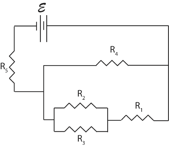
    a) Draw a possible circuit connected to a battery that has the above equivalent resistance. Clearly mark each resistor with \(R_1\), \(R_2\), \(R_3\), \(R_4\), and \(R_5\).

    b)  Assume that  \(R_{eq}=25\Omega\), \(R_4=R_1+\Big(\dfrac{1}{R_2}+\dfrac{1}{R_3}\Big)^{-1}\), and \(R_2=2R_3\). If the circuit is connected to a 10V battery, how much current will flow through \(R_2\)?  

    c) If \(R_2\) was shorted out, what would be the new equivalent resistance in terms of the resistor numbers?  Would the total current coming out of the battery increase, decrease, or stay the same?  

     
    Solution

    a) The equation above states that \(R_5\) is in series with a parallel branch which contains \(R_4\) in one path and \(R_1+\Big(\dfrac{1}{R_2}+\dfrac{1}{R_3}\Big)^{-1}\) in the other. The other path has \(R_1\) in series with a parallel branch containing \(R_2\) and \(R_3\) as shown.

    electric-circuit2.png

    b) The total current coming out of the battery is

    \(I=\dfrac{\mathcal E}{R_{eq}}=\dfrac{10V}{25\Omega}=0.4A\)

    The two paths of the main parallel branch have equal resistance, so the current will split equally at the junction. This means that half the total current will flow through \(R_1\), which is \(0.2 A\).  The current will split further between \(R_2\) and \(R_3\). Since \(R_2=2R_3\), \(R_3\) will get double the current of \(R_2\) since their voltage drops have to be the same.

    \(\Delta V_2=\Delta V_3\)

    \(I_2R_3=I_3R_3\)

    \(I_2=\dfrac{I_3}{2}\)

    Using the fact that \(I_2+I_3=0.2A\) and the above result we get:

    \(I_2=\dfrac{I_3}{2}=\dfrac{0.2-I_2}{2}\)

    Resulting in \(I_2=\dfrac{1}{15}A\).

    c) If \(R_2\) was shorted out, all the current going through \(R_1\) would go though the wire, so \(R_2\) and \(R_3\) would not get any current and are no longer part of the active circuit.  The new equivalent resistance becomes:

    \(R_{eq}=R_5+\Big(\dfrac{1}{R_4}+\dfrac{1}{R_1}\Big)^{-1}\)

    Since the lower branch now has reduced resistance, the combined resistance between \(R_4\) and the lower branch will decrease, thus the total equivalent resistance of the entire circuit will be decreased. Smaller total resistance means that the total current will increase since, \(I=\dfrac{\mathcal E}{R_{eq}}\).


    Example \(\PageIndex{3}\)

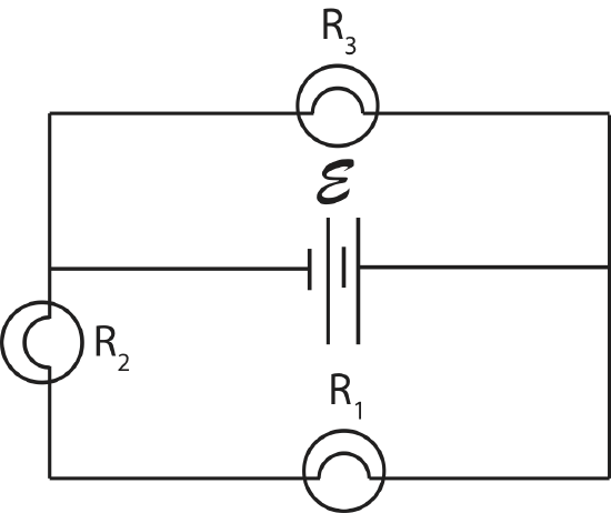
    You build the circuit shown here and find that the brightness of light bulb 1 twice as bright (double power) as 3, and the brightness of light bulb 1 is half as bright as 2 (half power).

    electric-circuit1.png

    a) You know that light bulb 3 has resistance of \(36\Omega\).  Find the resistance of light bulbs 1 and 2. 

    b) You add a wire across light bulb 1. Describe what happens to the brightness of each light bulb (gets brighter, gets dimmer, stays the same brightness, or is not lit) compared to the original circuit. 

    c) If light bulb 1 in the original circuit burnt out instead, what happens to the brightness of each light bulb (gets brighter, gets dimmer, stays the same brightness, or is not lit) compared to the original circuit? 

     
    Solution

    a) Resistors \(R_1\) and \(R_2\) have the same current since they are in series, \(I_1=I_2\).  Since \(P=I^2R\) and \(P_2=2P_1\) we conclude that:

    \(P_2=I^2R_2=2P_1=2I^2R_1\)

    \(R_2=2R_1\)

    When it comes to resistors in parallel, it is often simpler to think in terms of voltage drops rather than current. The voltage drop across \(R_3\) has to equal to the voltage drop across the other branch which includes the sum of voltage drop across \(R_1\) and \(R_2\):

    \(\Delta V_3=\Delta V_1+\Delta V_2\)

    Since \(R_2=2R_1\) and \(\Delta V=-IR\),  \(\Delta V_2=2\Delta V_1\), and the above equation becomes:

    \(\Delta V_3=3\Delta V_1\)

    We also know that \(P_1=2P_3\).  Using \(P=\dfrac{\Delta V^2}{R}\) we find that:

    \(\dfrac{\Delta V_1^2}{R_1}=2\dfrac{\Delta V_3^2}{R_3}\)

    Using the result \(\Delta V_3=3\Delta V_1\) we find that:

    \(\dfrac{\Delta V_1^2}{R_1}=18\dfrac{\Delta V_1^2}{R_3}\)

    \(R_3=18R_1\)

    Using \(R_3=36\Omega\), we find that \(R_1=2\Omega\), and using \(R_2=2R_1\), we find that \(R_2=4\Omega\).

    b) Adding a wire across \(R_1\) shorts out \(R_1\), since all the current will go through the wire. So \(R_1\) will not be lit. The voltage drop across \(R_2\) has to increase, since  due to the loop rule applied to the bottom loop, all the voltage now drops across rather \(R_2\), \(\mathcal E=-\Delta V_2\), rather than being split between \(R_1\) and \(R_2\)  in the original circuit. Since power is proportional to voltage drop, 2 gets brighter. The voltage drop across \(R_3\) doesn’t change due to loop rule for top loop, \(\mathcal E=-\Delta V_3\), so 3 stays the same brightness.

    c) If light bulb 1 burns out, the path on the lower loop is broken (there is no place for current to go), so both \(R_1\) and \(R_2\) will not be lit. The voltage drop across \(R_3\) doesn’t change due to loop rule for top loop as in the argument for b), so 3 stays the same brightness.


    This page titled 8.7: Circuit Problem Solving is shared under a CC BY 4.0 license and was authored, remixed, and/or curated by Dina Zhabinskaya.