
3.2: Location, Location, Location


- Last updated
- Feb 20, 2023
- Save as PDF

( \newcommand{\kernel}{\mathrm{null}\,}\)
Members of the Stargazers Club decide to look at some galaxies. It is a very dark night at Crystal Lake, and they are disappointed that their photos do not look as good as ones they have seen on the internet.
- Aaron: “When I look at a galaxy through the 8-inch telescope that we brought, I can’t see anything but a fuzzy blob. What am I doing wrong?”
- Bonnie hooks up her digital camera to her telescope and tries to take a photo. She complains: “Well, at least this looks like a galaxy. But it is certainly nowhere near as sharp as pictures from the Hubble telescope.”
- Camille: “That’s because Hubble has a bigger mirror than our telescope, so it can catch more light.”
Login with LibreOne to view this question
NOTE: If you typically access ADAPT assignments through an LMS like Canvas, you should open this page there.
Login with LibreOne to view this question
NOTE: If you typically access ADAPT assignments through an LMS like Canvas, you should open this page there.
Login with LibreOne to view this question
NOTE: If you typically access ADAPT assignments through an LMS like Canvas, you should open this page there.
Two more students join the conversation.
- Mark: “You know, if we had really big telescopes, like the Keck Telescope in Hawaii, I bet we could see those galaxies really well.”
- Nina: “Wait, so if they went to all the trouble to build a huge telescope like Keck, why didn’t they put it in space?”
Login with LibreOne to view this question
NOTE: If you typically access ADAPT assignments through an LMS like Canvas, you should open this page there.
Login with LibreOne to view this question
NOTE: If you typically access ADAPT assignments through an LMS like Canvas, you should open this page there.
Login with LibreOne to view this question
NOTE: If you typically access ADAPT assignments through an LMS like Canvas, you should open this page there.
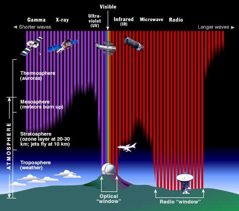
EARTH’S ATMOSPHERE BLOCKS CERTAIN WAVELENGTHS
Not all wavelengths of light penetrate through Earth’s atmosphere to the ground. Certain wavelengths of radio are absorbed, as are those in the far infrared. In fact, most of what penetrates our atmosphere and reaches the ground is the very narrow band of visible light and a large portion of the radio spectrum. Everything else is stopped high above. This is illustrated by Figure 3.7.
.jpg?revision=1)
To observe high-energy radiation from celestial objects, specialized telescopes must be put on balloons or sub-orbital rockets that carry them to the highest reaches of the atmosphere. Better yet, we can launch them into orbit as free-flying satellites. From there, they can observe the cosmos completely free of atmospheric absorption. Almost all gamma-ray, x-ray, and ultraviolet observatories are on satellites launched into space, as are some of the infrared observatories. High-energy photons are so reactive that long before they reach the surface, they are absorbed by molecules in the upper atmosphere. This is a good thing. Exposure to all of these high-energy photons is harmful, or in some cases, fatal to humans. Only some of the lower-energy ultraviolet penetrates to the ground and contributes to sunburn - and skin cancer.
Not all of the blocked light must be studied from space, however. Sometimes, it is just necessary to get high enough in the atmosphere that you are above the absorbing layer. This is true for much of the near-infrared and microwave regions. The primary atmospheric constituent that absorbs these bands is water, but other molecules absorb them as well. Water in the atmosphere is mostly below about 3,000 m, so telescopes that are used to study the near-infrared and microwave parts of the spectrum can be placed either on high mountaintops or on airplanes that fly at high altitudes.
EARTH’S ATMOSPHERE MAKES IMAGES BLURRY
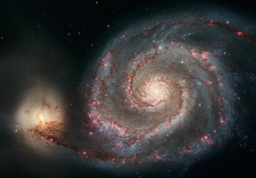
Even for wavelengths of light that are not blocked, Earth’s atmosphere blurs the images. This blurring occurs because of turbulence and temperature differences, like the waviness you see in the air above a road on a hot day, or over a barbecue grill. For this reason, even optical telescopes are built on high mountaintops, a placement that puts them above a substantial fraction of the atmosphere and atmospheric pollution. This is also the reason the Hubble Space Telescope was placed in orbit above Earth’s atmosphere. Even though HST has a modest-sized mirror (2.4 m) compared to most modern research telescopes, it has superior resolution because of its location (Figures 3.8 and 3.9).

.jpg?revision=1)

The Hubble Space Telescope (HST) is an amazing observatory that acts as our eyes in space, allowing us to see the Universe in incredible detail—you have probably seen some HST images already. Named for astronomer Edwin Hubble, the HST is part of NASA's spectrum. The Hubble Space Telescope was launched during April 1990 from the Space Shuttle Discovery and celebrated its 20th birthday in April 2010. Unlike the other three Great Observatories, HST was designed to be serviced and repaired by astronauts while in space. This has been accomplished with great success on several occasions during Hubble's lifetime. Because of this ability, Hubble's equipment has been continually upgraded, allowing for clearer high-resolution images of the deepest reaches of the Universe. Now, you might be wondering, "How far into space can the Hubble see?" The HST has seen galaxies farther away than 12 billion light years! One such image is called the Hubble Ultra Deep Field (HUDF), shown in Figure B.2. The HUDF has provided astronomers around the world with a wealth of new and exciting information about the Universe.
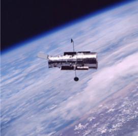
HST is located 353 miles (569 km) above Earth, circling the planet every 97 minutes. The telescope has a 2.4-m-diameter primary mirror and a 0.3-m (~12 inches)-diameter secondary mirror that direct the collected light onto the focal plane where it is analyzed by the science instruments. Compared to telescopes on the ground, these are not large mirrors; but because Hubble is above Earth's atmosphere, the mirrors can collect light without interference. HST is powered by two solar arrays that convert sunlight into electricity, much like solar pictures you often see in news reports. Two of these, the Wide-Field Planetary Camera 3 (WFPC 3) and the Advanced Camera for Surveys (ACS), observe in the optical. The other, called the Near Infrared Camera and Multi-Object Spectrometer (NICOMOS), observes in the near infrared; it can both image and take spectra. In addition to the imagers, there are two spectrometers. The first is the Space Telescope Imaging Spectrometer (STIS), and as its name implies, it can both image and take spectra, though it is primarily a spectrometer. The other spectrometer is the Cosmic Origins Spectrograph (COS). Both work in the optical and ultraviolet parts of the spectrum. Of these instruments, COS and WFPC 3 were delivered by the Space Shuttle on the final Hubble servicing mission in May 2009. STIS received a major overhaul during that same mission.

To learn more about HST, visit the following:
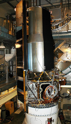
On July 23, 1999, NASA launched the Advanced X-ray Astophysics Facility, or AXAF, as the second in its Great Obervatories program. The observatory was first proposed in 1977, and the intervening 22 years had seen its design go through several changes. Nonetheless, the observatory was, and continues to be, the most sesitive x-ray observatory ever built in terms of angular and spectral resolution. It studies x-rays with energies between about 0.12 and 12 keV (wavelengths from 0.1 to 10nm).
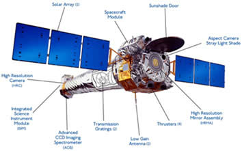
After its launch and 60-day shakedown phase, the observatory was christened the Chandra X-ray Observatory, after Subramanyan Chandrasekhar, the late Indian astrophysicist, former professor at the University of Chicago and Nobel Prize laureate. Chandra, as he was known, is considered to have been one of the foremost astrophysicists of the 20th century.
The Chandra X-ray Observatory hosts both imaging and spectroscopic capabilities. Its eight Wolter mirrors focus x-rays onto a focal plane where detectors from Chandra’s four different instruments can be placed. The high-resolution camera (HRC) allows detailed images to be taken. Its angular resolution is about half an arcsecond, or about twice that of the average human eye. Unlike the HRC, the advanced CCD imaging spectrometer (ACIS) uses CCD arrays to detect x-rays. Because Chandra is in a highly eccentric orbit around Earth, taking it from 16,000 km to 133,000 km altitudes, the telescope is able to make much longer exposures than telescopes in low Earth orbit.

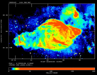
Click on http://chandra.harvard.edu/photo/2002/0052/ to learn more about this photo. Credit: NASA/CXC/ASU/J. Hester et al.
To learn more, visit the Chandra website:
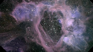
The Spitzer Space Telescope is the last in the series of NASA’s four Great Observatories. It observes in the infrared (IR) part of the spectrum between 3 and 180 microns (1 micron = 10-6 m). Spitzer was launched in August 2003.
Spitzer allows astronomers to study what they deem “cool” and “warm” objects. These are objects that have temperatures ranging from around zero degrees Celsius to a few thousand degrees Celsius. Such objects are primarily emitters of IR radiation. These objects include stars cooler than the Sun, substellar objects called brown dwarfs, planets, and warm clouds of dust in the Milky Way and other galaxies. But Spitzer is useful for more than just looking at warm objects. IR wavelengths of light can easily pass through clouds that are entirely opaque at visible wavelengths. Astronomers can use IR observations to peer behind these clouds to study stellar nurseries and the center of our Galaxy. In addition, the most distant galaxies in the Universe have their light stretched to IR wavelengths by the expansion of the Universe; thus, we must observe them in IR wavelengths if we wish to see the stellar activity within them.
Spitzer must be cooled to only a few degrees above absolute zero because it observes radiation that is emitted by warm objects. As a result, if the telescope is not cooled, its own radiation will swamp the emission from the astronomical objects it is used to study. This cooling requirement is what places the strongest constraint on the duration of the mission: The spacecraft is cooled by boiling off liquid helium to a temperature only a few degrees above absolute zero (–273 oC). Once the helium is exhausted, the cooled portion of the mission comes to an end. Spitzer reached this milestone in May 2009, after which it has been operated in “warm mode.” Some of the science remains the same in warm mode, namely, at the shorter IR wavelengths. However, the telescope is no longer able to study longer IR wavelengths beyond about 5 microns.
The cool stage of the mission was greatly extended by using an innovative orbit. Rather than orbit Earth, which is quite a warm object, Spitzer was put into a solar orbit that causes it to slowly drift away from Earth. This tactic had several advantages. First, it greatly expanded the fraction of the sky that was available to observe at any given time. Spitzer generally cannot point closer than about 90 degrees away from bright objects like the Sun, Earth, and Moon. However, because its orbit carried it so far from Earth and Moon, those bodies became unimportant for pointing the telescope. In addition, the telescope could be cooled all the way down to –242 oC by space itself, before any helium was needed. This allowed less helium to be used, lowering the weight of the spacecraft and, as a result, the cost of the mission.

To learn more, visit the Spitzer website:
The Gemini Observatory is a pair of 8.1-meter telescopes, one located in the northern hemisphere and one located in the south. The telescopes are located in two of the best observing sites in the world, Mauna Kea in Hawaii and the Andes Mountains of northern Chile. They are optical/near infrared telescopes and were built and are operated by a consortium of seven partner countries: the United States, United Kingdom, Canada, Chile, Australia, Brazil, and Argentina. Both telescopes began science observations circa 2000.
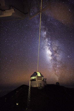
The Gemini telescopes were designed to carry out diverse observing programs in the near-infrared part of the spectrum, as well as the optical. Their locations in high and dry settings means that they are not much hampered by atmospheric water vapor, which strongly absorbs IR radiation. In addition, their mirrors are coated with silver, using a special process that enhances their IR performance. They are also able to use techniques of adaptive optics to correct for atmospheric turbulence, greatly increasing the sharpness of their images. Both Gemini locations have dark skies, making it possible for the telescopes to view faint objects.
The Gemini telescopes have a complement of state-of-the-art cameras and instruments that allow astronomers to take images and spectra of stars, galaxies, and other astronomical objects. One type of new technology used in both telescopes is adaptive optics, which can greatly improve the resolution of the images we take with ground-based telescopes. In an adaptive-optics system, astronomers use a wavefront sensor to model the blurring effects of Earth’s atmosphere on light from a reference star (or at some telescopes, the blurring is measured from a spot made by a laser). This information is fed to a deformable mirror, which can rapidly change its shape and be used to counteract the atmospheric blurring, resulting in a sharper image.
Turbulence from the atmosphere changes at a rapid rate, so the adaptive-optics system must constantly update the correction applied by the deformable mirror. In typical adaptive-optics systems, these corrections are made hundreds to thousands of times per second; you can actually hear the deformable mirror whirring as it rapidly adjusts and readjusts. Adaptive optics has only been used regularly in telescopes since about 2000 and has mainly been developed for use with near-infrared observations. Astronomers are now pushing toward visible-light adaptive optics systems, and future space-based observatories may also make use of similar technologies. For instance, adaptive optics could correct for optical distortions due to the motion of the telescopes themselves as they orbit Earth or travel toward other planets.
To learn more, visit the Gemini website:
The Very Large Array (VLA) radio observatory is one of the premiere astronomical facilities in the world. It is also one of the most productive scientific instruments of the past 30 years. The VLA consists of 27 separate parabolic antennas, each with a diameter of 25 m. The antennas can be moved along a system of railroad tracks, allowing the array to adjust its size from a 1-km diameter, in “D” configuration, up to a 36-km diameter in the “A” configuration. Two additional configurations have intermediate sizes. The array is sensitive to different angular sizes on the sky in the different configurations, having a maximum angular resolution of 0.04 arcseconds in the A array, comparable to that of the Hubble Space Telescope. The array is located at an elevation of 7,000 feet on the plains of San Agustin in New Mexico, far away from sources of radio noise like radio and TV stations and electrical appliances.
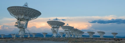
The VLA is a type of telescope called an interferometer. It combines the signals from its antennas electronically to create a single image. To achieve this feat, the distances between any two pairs of antennas must be known to a fraction of a wavelength. The timing of arrival of the radio signals at each antenna must also be known. The wavefront can then be reconstructed to provide an image of comparable quality to one made by a single dish with a diameter equal to the largest antenna separation in the array. Of course, since the synthetic dish created by all combined antennas is mostly empty, the VLA sensitivity is much lower than a filled dish of the same diameter. Only its angular resolution is comparable. Nonetheless, it is far less costly to build many small antennas and then to combine their signals than it is to attempt to build one very large antenna: Consider the difficulties encountered in trying to build a single, steerable dish 27 km in diameter, and it will be clear why astronomers chose an array of smaller dishes instead.
The VLA is sensitive to radio wavelengths from about 4 m down to 7 mm (frequencies from 70 MHz to 50 GHz, respectively), though the coverage is not complete in this region. In addition to making broadband observations, the telescope can observe individual spectral lines from atoms and molecules. This capability allows detailed studies to be made of the velocity structure of gas in galaxies, including our own, as well as its spatial distribution, for example.
To learn more, visit the National Radio Astronomy Observatory website:
Including the section about the VLA:
COST
While it is possible, and sometimes even desirable, to go high into the atmosphere or into space, there are disadvantages in terms of cost and convenience. For example, servicing Hubble required expensive and risky Space Shuttle missions. Compare this requirement to simply driving to the top of a mountain, even if that mountain is in a remote desert location in northern Chile. Typically, the difficulty and expense related to working in space means that only telescopes that absolutely must be placed there to achieve the desired science goals are launched into orbit or beyond.
DARK SKIES
Most observatories are built in remote locations. This is true even for telescopes that detect optical and radio light, which easily reaches the ground. These locations are necessary because of city lights, weather, and radio interference from electrical circuits, cell phones, etc. The growing problem of “light pollution” (as illustrated in Figure 3.10) has led to great losses in sensitivity from historical telescopes that are now located too close to population centers. It has also led to laws in cities such as Tucson (near the National Optical Astronomy Observatory’s Kitt Peak) to try to limit the amount of light that can be directed into the sky at night. Tucson passed these ordinances in 1972, and they have been modified many times since then. As a result, Tucson is one of the few major cities where it is still possible to see the Milky Way galaxy with the naked eye.

The Globe at Night project tracks sky brightness around the world. The International Dark Sky Association advocates and educates for dark skies through environmentally responsible outdoor lighting.
To get funding to build telescopes and use them to do observations, astronomers usually write proposals that are reviewed by committees composed of other astronomers. In this activity, your role is to be a member of a review committee, and your goal is to rate the scientific merit and feasibility of each proposal, to provide advice to the government official who controls the funding.
The table below summarizes the wavelength of the light, the target object the astronomers will study, and the size and location of the telescope that they propose to build.
| PROPOSAL NUMBER | WAVELENGTH | TARGET OBJECT | DIAMETER OF TELESCOPE | LOCATION (ALTITUDE) |
|---|---|---|---|---|
| 1 | Radio | Jupiter | 100 m | West Virginia (900 m) |
| 2 | Infrared | Surface of a neutron star | 1 m | Chicago (175 m) |
| 3 | Microwave | Sun | 3.5 m | Underground mine (1,000 m below Earth’s surface) |
| 4 | Visible | Distant galaxies | 2.4 m | Earth orbit (300 km) |
| 5 | Ultraviolet | Quasars | 1 m | Mountain in Hawaii (4,000 m) |
| 6 | X-ray | Supernova | 25 cm | High-altitude balloon (25 km) |
| 7 | Gamma-ray | Exoplanet | 10 cm | Suborbital rocket (550 km peak trajectory) |
1. To help you decide which proposal(s) to fund, consider the following criteria:
- Does the proposed object emit light in the indicated wavelength band?
- Will the proposed object be able to be detected if you build a telescope of the indicated size and put it in the specified location? (You might want to revisit Figure 3.7 for help with this part.)
Login with LibreOne to view this question
NOTE: If you typically access ADAPT assignments through an LMS like Canvas, you should open this page there.
Fill in the table below with a yes or no answer to each of these two criteria, and then decide if you would recommend funding the proposal.
Login with LibreOne to view this question
NOTE: If you typically access ADAPT assignments through an LMS like Canvas, you should open this page there.