
28.4: Bernoulli’s Principle
- Page ID
- 25566
\( \newcommand{\vecs}[1]{\overset { \scriptstyle \rightharpoonup} {\mathbf{#1}} } \)
\( \newcommand{\vecd}[1]{\overset{-\!-\!\rightharpoonup}{\vphantom{a}\smash {#1}}} \)
\( \newcommand{\dsum}{\displaystyle\sum\limits} \)
\( \newcommand{\dint}{\displaystyle\int\limits} \)
\( \newcommand{\dlim}{\displaystyle\lim\limits} \)
\( \newcommand{\id}{\mathrm{id}}\) \( \newcommand{\Span}{\mathrm{span}}\)
( \newcommand{\kernel}{\mathrm{null}\,}\) \( \newcommand{\range}{\mathrm{range}\,}\)
\( \newcommand{\RealPart}{\mathrm{Re}}\) \( \newcommand{\ImaginaryPart}{\mathrm{Im}}\)
\( \newcommand{\Argument}{\mathrm{Arg}}\) \( \newcommand{\norm}[1]{\| #1 \|}\)
\( \newcommand{\inner}[2]{\langle #1, #2 \rangle}\)
\( \newcommand{\Span}{\mathrm{span}}\)
\( \newcommand{\id}{\mathrm{id}}\)
\( \newcommand{\Span}{\mathrm{span}}\)
\( \newcommand{\kernel}{\mathrm{null}\,}\)
\( \newcommand{\range}{\mathrm{range}\,}\)
\( \newcommand{\RealPart}{\mathrm{Re}}\)
\( \newcommand{\ImaginaryPart}{\mathrm{Im}}\)
\( \newcommand{\Argument}{\mathrm{Arg}}\)
\( \newcommand{\norm}[1]{\| #1 \|}\)
\( \newcommand{\inner}[2]{\langle #1, #2 \rangle}\)
\( \newcommand{\Span}{\mathrm{span}}\) \( \newcommand{\AA}{\unicode[.8,0]{x212B}}\)
\( \newcommand{\vectorA}[1]{\vec{#1}} % arrow\)
\( \newcommand{\vectorAt}[1]{\vec{\text{#1}}} % arrow\)
\( \newcommand{\vectorB}[1]{\overset { \scriptstyle \rightharpoonup} {\mathbf{#1}} } \)
\( \newcommand{\vectorC}[1]{\textbf{#1}} \)
\( \newcommand{\vectorD}[1]{\overrightarrow{#1}} \)
\( \newcommand{\vectorDt}[1]{\overrightarrow{\text{#1}}} \)
\( \newcommand{\vectE}[1]{\overset{-\!-\!\rightharpoonup}{\vphantom{a}\smash{\mathbf {#1}}}} \)
\( \newcommand{\vecs}[1]{\overset { \scriptstyle \rightharpoonup} {\mathbf{#1}} } \)
\(\newcommand{\longvect}{\overrightarrow}\)
\( \newcommand{\vecd}[1]{\overset{-\!-\!\rightharpoonup}{\vphantom{a}\smash {#1}}} \)
\(\newcommand{\avec}{\mathbf a}\) \(\newcommand{\bvec}{\mathbf b}\) \(\newcommand{\cvec}{\mathbf c}\) \(\newcommand{\dvec}{\mathbf d}\) \(\newcommand{\dtil}{\widetilde{\mathbf d}}\) \(\newcommand{\evec}{\mathbf e}\) \(\newcommand{\fvec}{\mathbf f}\) \(\newcommand{\nvec}{\mathbf n}\) \(\newcommand{\pvec}{\mathbf p}\) \(\newcommand{\qvec}{\mathbf q}\) \(\newcommand{\svec}{\mathbf s}\) \(\newcommand{\tvec}{\mathbf t}\) \(\newcommand{\uvec}{\mathbf u}\) \(\newcommand{\vvec}{\mathbf v}\) \(\newcommand{\wvec}{\mathbf w}\) \(\newcommand{\xvec}{\mathbf x}\) \(\newcommand{\yvec}{\mathbf y}\) \(\newcommand{\zvec}{\mathbf z}\) \(\newcommand{\rvec}{\mathbf r}\) \(\newcommand{\mvec}{\mathbf m}\) \(\newcommand{\zerovec}{\mathbf 0}\) \(\newcommand{\onevec}{\mathbf 1}\) \(\newcommand{\real}{\mathbb R}\) \(\newcommand{\twovec}[2]{\left[\begin{array}{r}#1 \\ #2 \end{array}\right]}\) \(\newcommand{\ctwovec}[2]{\left[\begin{array}{c}#1 \\ #2 \end{array}\right]}\) \(\newcommand{\threevec}[3]{\left[\begin{array}{r}#1 \\ #2 \\ #3 \end{array}\right]}\) \(\newcommand{\cthreevec}[3]{\left[\begin{array}{c}#1 \\ #2 \\ #3 \end{array}\right]}\) \(\newcommand{\fourvec}[4]{\left[\begin{array}{r}#1 \\ #2 \\ #3 \\ #4 \end{array}\right]}\) \(\newcommand{\cfourvec}[4]{\left[\begin{array}{c}#1 \\ #2 \\ #3 \\ #4 \end{array}\right]}\) \(\newcommand{\fivevec}[5]{\left[\begin{array}{r}#1 \\ #2 \\ #3 \\ #4 \\ #5 \\ \end{array}\right]}\) \(\newcommand{\cfivevec}[5]{\left[\begin{array}{c}#1 \\ #2 \\ #3 \\ #4 \\ #5 \\ \end{array}\right]}\) \(\newcommand{\mattwo}[4]{\left[\begin{array}{rr}#1 \amp #2 \\ #3 \amp #4 \\ \end{array}\right]}\) \(\newcommand{\laspan}[1]{\text{Span}\{#1\}}\) \(\newcommand{\bcal}{\cal B}\) \(\newcommand{\ccal}{\cal C}\) \(\newcommand{\scal}{\cal S}\) \(\newcommand{\wcal}{\cal W}\) \(\newcommand{\ecal}{\cal E}\) \(\newcommand{\coords}[2]{\left\{#1\right\}_{#2}}\) \(\newcommand{\gray}[1]{\color{gray}{#1}}\) \(\newcommand{\lgray}[1]{\color{lightgray}{#1}}\) \(\newcommand{\rank}{\operatorname{rank}}\) \(\newcommand{\row}{\text{Row}}\) \(\newcommand{\col}{\text{Col}}\) \(\renewcommand{\row}{\text{Row}}\) \(\newcommand{\nul}{\text{Nul}}\) \(\newcommand{\var}{\text{Var}}\) \(\newcommand{\corr}{\text{corr}}\) \(\newcommand{\len}[1]{\left|#1\right|}\) \(\newcommand{\bbar}{\overline{\bvec}}\) \(\newcommand{\bhat}{\widehat{\bvec}}\) \(\newcommand{\bperp}{\bvec^\perp}\) \(\newcommand{\xhat}{\widehat{\xvec}}\) \(\newcommand{\vhat}{\widehat{\vvec}}\) \(\newcommand{\uhat}{\widehat{\uvec}}\) \(\newcommand{\what}{\widehat{\wvec}}\) \(\newcommand{\Sighat}{\widehat{\Sigma}}\) \(\newcommand{\lt}{<}\) \(\newcommand{\gt}{>}\) \(\newcommand{\amp}{&}\) \(\definecolor{fillinmathshade}{gray}{0.9}\)Let’s again consider the case of an ideal fluid that undergoes steady flow and apply energy methods to find an equation of state that relates pressure, density, and speed of the flow at different points in the fluid. Let’s examine the case of a steady horizontal flow in as seen in the overhead view shown in Figure 28.6. We represent this flow by streamlines and a flow tube associated with the streamlines. Let’s consider the motion of a fluid particle along one streamline passing through points A and B in Figure 28.6. The cross sectional area of the flow tube at point A is less than the cross-sectional area of the flow tube at point B.
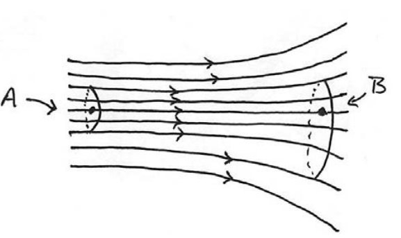
According to Equation (28.3.5), the particle located at point A has a greater speed than a fluid particle located at point B . Therefore a particle traveling along the streamline from point A to point B must decelerate. Because the streamline is horizontal, the force responsible is due to pressure differences in the fluid. Thus, for this steady horizontal flow in regions of lower speed there must be greater pressure than in regions of higher speed. Now suppose the steady flow of the ideal fluid is not horizontal, with the y -representing the vertical directi. The streamlines and flow tube for this steady flow are shown in Figure 28.7.
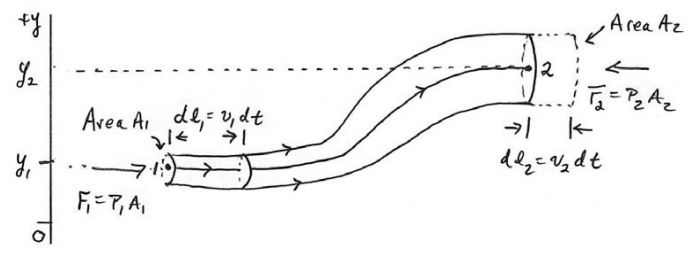
In order to determine the equation relating the pressure, speed and height difference of the tube, we shall use the work-energy theorem. We take as a system the mass contained in the flow tube shown in Figure 28.7. The external forces acting on our system are due to the pressure acting at the two ends of the flow tube and the gravitational force. Consider a streamline passing through points 1 and 2 at opposite ends of the flow tube. Let’s assume that the flow tube is narrow enough such that the velocity of the fluid is uniform on the cross-sectional areas of the tube at points 1 and 2 . At point 1, denote the speed of a fluid particle by \(v_{1}\), the cross-sectional area by \(A_{1}\), the fluid pressure by \(P_{1}\), and the height of the center of the cross-sectional area by \(y_{1}\). At point 2 , denote the speed of a fluid particle by \(v_{2}\), the cross-sectional area by \(A_{2}\), the fluid pressure by \(P_{2}\), and the height of the center of the cross-sectional area by \(y_{2}\).
Consider the flow tube at time t as illustrated in Figure 28.7. At the left end of the flow, in a time interval \(d t\), a particle at point 1 travels a distance \(d l_{1}=v_{1} d t\). Therefore a small volume \(d V_{1}=A_{1} d l_{1}=A_{1} v_{1} d t\) of fluid is displaced at the right end of the flow tube. In a similar fashion, at particle at point 2 , travels a distance \(d l_{2}=v_{2} d t\). Therefore a small volume of fluid \(d V_{2}=A_{2} d l_{2}=A_{2} v_{2} d t\) is also displaced to the right in the flow tube during the time interval \(d t\). Because we are assuming the fluid is incompressible, by Equation(28.3.5), these volume elements are equal, \(d V \equiv d V_{1}=d V_{2}\).
There is a force of magnitude \(F_{1}=P_{1} A_{1}\) in the direction of the flow arising from the fluid pressure at the left end of the tube acting on the mass element that enters the tube. The work done displacing the mass element is then
\[d W_{1}=F_{1} d l_{1}=P_{1} A_{1} d l_{1}=P_{1} d V \nonumber \]
There is also a force of magnitude \(F_{2}=P_{2} A_{2}\) in the direction opposing the flow arising 2 2 2 from the fluid pressure at the right end of the tube. The work done opposing the displacement of the mass element leaving the tube is then
\[d W_{1}=-F_{2} d l_{2}=-P_{2} A_{2} d l_{2}=-P_{2} d V \nonumber \]
Therefore the external work done by the force associated with the fluid pressure is the sum of the work done at each end of the tube
\[d W^{e x t}=d W_{1}+d W_{2}=\left(P_{1}-P_{2}\right) d V \nonumber \]
In a time interval dt , the work done by the gravitational force is equal to
\[d W^{g}=-d m g\left(y_{2}-y_{1}\right)=-\rho d V g\left(y_{2}-y_{1}\right) \nonumber \]
Because we only chose the mass in the flow tube as our system, and we assumed that the fluid was ideal (no frictional losses due to viscosity) the change in the potential energy of the system is
\[d U=-W^{g}=\rho d V g\left(y_{2}-y_{1}\right) \nonumber \]
At time t , the kinetic energy of the system is the sum of the kinetic energy of the small mass element of volume \(d V=A_{1} d l_{1}\) moving with speed v1 and the rest of the mass in the flow tube. At time \(t+d t\), the kinetic energy of the system is the sum of the kinetic energy of the small mass element of volume \(d V=A_{2} d l_{2}\) moving with speed \(v_{2}\) and the rest of the mass in the flow tube. The change in the kinetic energy of the system is due to the mass elements at the two ends and therefore
\[d K=\frac{1}{2} d m_{2} v_{2}^{2}-\frac{1}{2} d m_{1} v_{1}^{2}=\frac{1}{2} \rho d V\left(v_{2}^{2}-v_{1}^{2}\right) \nonumber \]
The work-energy theorem \(d W^{e x t}=d U+d K\) for system is then
\[\left(P_{1}-P_{2}\right) d V=\frac{1}{2} \rho d V\left(v_{2}^{2}-v_{1}^{2}\right)+\rho g\left(y_{2}-y_{1}\right) d V \nonumber \]
We now divide Equation (28.4.7) through by the volume \(d V\) and rearrange terms, yielding
\[P_{1}+\rho g y_{1}+\frac{1}{2} \rho v_{1}^{2}=P_{2}+\rho g y_{2}+\frac{1}{2} \rho v_{2}^{2} \nonumber \]
Because points 1 and 2 were arbitrarily chosen, we can drop the subscripts and write Equation (28.4.8) as
\[P+\rho g y+\frac{1}{2} \rho v^{2}=\mathrm{constant} \text{ (ideal fluid, steady flow)} \nonumber \]
Equation (28.4.9) is known as Bernoulli’s Equation.