
28.5: Worked Examples- Bernoulli’s Equation
- Page ID
- 25567
\( \newcommand{\vecs}[1]{\overset { \scriptstyle \rightharpoonup} {\mathbf{#1}} } \)
\( \newcommand{\vecd}[1]{\overset{-\!-\!\rightharpoonup}{\vphantom{a}\smash {#1}}} \)
\( \newcommand{\dsum}{\displaystyle\sum\limits} \)
\( \newcommand{\dint}{\displaystyle\int\limits} \)
\( \newcommand{\dlim}{\displaystyle\lim\limits} \)
\( \newcommand{\id}{\mathrm{id}}\) \( \newcommand{\Span}{\mathrm{span}}\)
( \newcommand{\kernel}{\mathrm{null}\,}\) \( \newcommand{\range}{\mathrm{range}\,}\)
\( \newcommand{\RealPart}{\mathrm{Re}}\) \( \newcommand{\ImaginaryPart}{\mathrm{Im}}\)
\( \newcommand{\Argument}{\mathrm{Arg}}\) \( \newcommand{\norm}[1]{\| #1 \|}\)
\( \newcommand{\inner}[2]{\langle #1, #2 \rangle}\)
\( \newcommand{\Span}{\mathrm{span}}\)
\( \newcommand{\id}{\mathrm{id}}\)
\( \newcommand{\Span}{\mathrm{span}}\)
\( \newcommand{\kernel}{\mathrm{null}\,}\)
\( \newcommand{\range}{\mathrm{range}\,}\)
\( \newcommand{\RealPart}{\mathrm{Re}}\)
\( \newcommand{\ImaginaryPart}{\mathrm{Im}}\)
\( \newcommand{\Argument}{\mathrm{Arg}}\)
\( \newcommand{\norm}[1]{\| #1 \|}\)
\( \newcommand{\inner}[2]{\langle #1, #2 \rangle}\)
\( \newcommand{\Span}{\mathrm{span}}\) \( \newcommand{\AA}{\unicode[.8,0]{x212B}}\)
\( \newcommand{\vectorA}[1]{\vec{#1}} % arrow\)
\( \newcommand{\vectorAt}[1]{\vec{\text{#1}}} % arrow\)
\( \newcommand{\vectorB}[1]{\overset { \scriptstyle \rightharpoonup} {\mathbf{#1}} } \)
\( \newcommand{\vectorC}[1]{\textbf{#1}} \)
\( \newcommand{\vectorD}[1]{\overrightarrow{#1}} \)
\( \newcommand{\vectorDt}[1]{\overrightarrow{\text{#1}}} \)
\( \newcommand{\vectE}[1]{\overset{-\!-\!\rightharpoonup}{\vphantom{a}\smash{\mathbf {#1}}}} \)
\( \newcommand{\vecs}[1]{\overset { \scriptstyle \rightharpoonup} {\mathbf{#1}} } \)
\(\newcommand{\longvect}{\overrightarrow}\)
\( \newcommand{\vecd}[1]{\overset{-\!-\!\rightharpoonup}{\vphantom{a}\smash {#1}}} \)
\(\newcommand{\avec}{\mathbf a}\) \(\newcommand{\bvec}{\mathbf b}\) \(\newcommand{\cvec}{\mathbf c}\) \(\newcommand{\dvec}{\mathbf d}\) \(\newcommand{\dtil}{\widetilde{\mathbf d}}\) \(\newcommand{\evec}{\mathbf e}\) \(\newcommand{\fvec}{\mathbf f}\) \(\newcommand{\nvec}{\mathbf n}\) \(\newcommand{\pvec}{\mathbf p}\) \(\newcommand{\qvec}{\mathbf q}\) \(\newcommand{\svec}{\mathbf s}\) \(\newcommand{\tvec}{\mathbf t}\) \(\newcommand{\uvec}{\mathbf u}\) \(\newcommand{\vvec}{\mathbf v}\) \(\newcommand{\wvec}{\mathbf w}\) \(\newcommand{\xvec}{\mathbf x}\) \(\newcommand{\yvec}{\mathbf y}\) \(\newcommand{\zvec}{\mathbf z}\) \(\newcommand{\rvec}{\mathbf r}\) \(\newcommand{\mvec}{\mathbf m}\) \(\newcommand{\zerovec}{\mathbf 0}\) \(\newcommand{\onevec}{\mathbf 1}\) \(\newcommand{\real}{\mathbb R}\) \(\newcommand{\twovec}[2]{\left[\begin{array}{r}#1 \\ #2 \end{array}\right]}\) \(\newcommand{\ctwovec}[2]{\left[\begin{array}{c}#1 \\ #2 \end{array}\right]}\) \(\newcommand{\threevec}[3]{\left[\begin{array}{r}#1 \\ #2 \\ #3 \end{array}\right]}\) \(\newcommand{\cthreevec}[3]{\left[\begin{array}{c}#1 \\ #2 \\ #3 \end{array}\right]}\) \(\newcommand{\fourvec}[4]{\left[\begin{array}{r}#1 \\ #2 \\ #3 \\ #4 \end{array}\right]}\) \(\newcommand{\cfourvec}[4]{\left[\begin{array}{c}#1 \\ #2 \\ #3 \\ #4 \end{array}\right]}\) \(\newcommand{\fivevec}[5]{\left[\begin{array}{r}#1 \\ #2 \\ #3 \\ #4 \\ #5 \\ \end{array}\right]}\) \(\newcommand{\cfivevec}[5]{\left[\begin{array}{c}#1 \\ #2 \\ #3 \\ #4 \\ #5 \\ \end{array}\right]}\) \(\newcommand{\mattwo}[4]{\left[\begin{array}{rr}#1 \amp #2 \\ #3 \amp #4 \\ \end{array}\right]}\) \(\newcommand{\laspan}[1]{\text{Span}\{#1\}}\) \(\newcommand{\bcal}{\cal B}\) \(\newcommand{\ccal}{\cal C}\) \(\newcommand{\scal}{\cal S}\) \(\newcommand{\wcal}{\cal W}\) \(\newcommand{\ecal}{\cal E}\) \(\newcommand{\coords}[2]{\left\{#1\right\}_{#2}}\) \(\newcommand{\gray}[1]{\color{gray}{#1}}\) \(\newcommand{\lgray}[1]{\color{lightgray}{#1}}\) \(\newcommand{\rank}{\operatorname{rank}}\) \(\newcommand{\row}{\text{Row}}\) \(\newcommand{\col}{\text{Col}}\) \(\renewcommand{\row}{\text{Row}}\) \(\newcommand{\nul}{\text{Nul}}\) \(\newcommand{\var}{\text{Var}}\) \(\newcommand{\corr}{\text{corr}}\) \(\newcommand{\len}[1]{\left|#1\right|}\) \(\newcommand{\bbar}{\overline{\bvec}}\) \(\newcommand{\bhat}{\widehat{\bvec}}\) \(\newcommand{\bperp}{\bvec^\perp}\) \(\newcommand{\xhat}{\widehat{\xvec}}\) \(\newcommand{\vhat}{\widehat{\vvec}}\) \(\newcommand{\uhat}{\widehat{\uvec}}\) \(\newcommand{\what}{\widehat{\wvec}}\) \(\newcommand{\Sighat}{\widehat{\Sigma}}\) \(\newcommand{\lt}{<}\) \(\newcommand{\gt}{>}\) \(\newcommand{\amp}{&}\) \(\definecolor{fillinmathshade}{gray}{0.9}\)Example \(\PageIndex{1}\): Venturi Meter
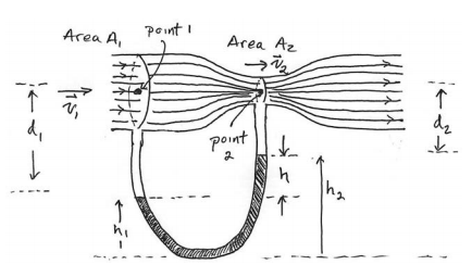
Figure 28.8 shows a Venturi Meter, a device used to measure the speed of a fluid in a pipe. A fluid of density \(\rho_{f}\) is flowing through a pipe. A U-shaped tube partially filled with mercury of density \(\rho_{Hg}\) lies underneath the points 1 and 2.
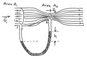
The cross-sectional areas of the pipe at points 1 and 2 are \(A_{1}\) and \(A_{2}\) respectively. Determine an expression for the flow speed at the point 1 in terms of the cross-sectional areas \(A_{1}\) and \(A_{2}\), and the difference in height h of the liquid levels of the two arms of the U-shaped tube.
Solution
We shall assume that the pressure and speed are constant in the cross-sectional areas \(A_{1}\) and \(A_{2}\). We also assume the fluid is incompressible so the density \(\rho_{f}\) is constant throughout the tube. The two points 1 and 2 lie on the streamline passing through the midpoint of the tube so they are at the same height. Using \(y_{1}=y_{2}\) in Equation (28.4.8), the pressure and flow speeds at the two points 1 and 2 are related by
\[P_{1}+\frac{1}{2} \rho_{f} v_{1}^{2}=P_{2}+\frac{1}{2} \rho_{f} v_{2}^{2} \nonumber \]
We can rewrite Equation (28.4.10) as
\[P_{1}-P_{2}=\frac{1}{2} \rho_{f}\left(v_{2}^{2}-v_{1}^{2}\right) \nonumber \]
Let h1 and h2 denote the heights of the liquid level in the arms of the U-shaped tube directly beneath points 1 and 2 respectively. Pascal’s Law relates the pressure difference between the two arms of the U-shaped tube according to in the left arm of the U-shaped tube according to
\[P_{\text {bottom}}=P_{1}+\rho_{f} g d_{1}+\rho_{H g} g h_{1} \nonumber \]
In a similar fashion, the pressure at point 2 is given by
\[P_{\text {bottom}}=P_{2}+\rho_{f} g d_{2}+\rho_{H g} g h_{2} \nonumber \]
Therefore, setting Equation (28.4.12) equal to Equation (28.4.13), we determine that the pressure difference on the two sides of the U-shaped tube is
\[P_{1}-P_{2}=\rho_{f} g\left(d_{2}-d_{1}\right)+\rho_{H g} g\left(h_{2}-h_{1}\right) \nonumber \]
From Figure 28.8, \(d_{2}+h_{2}=d_{1}+h_{1}\), therefore \(d_{2}-d_{1}=h_{1}-h_{2}=-h\) We can rewrite Equation (28.4.14) as
\[P_{1}-P_{2}=\left(\rho_{H g}-\rho_{f}\right) g h \nonumber \]
Substituting Equation (28.4.11) into Equation (28.4.15) yields
\[\frac{1}{2} \rho_{f}\left(v_{2}^{2}-v_{1}^{2}\right)=\left(\rho_{H g}-\rho_{f}\right) g h \nonumber \]
The mass continuity condition (Equation(28.3.5)) implies that \(v_{2}=\left(A_{1} / A_{2}\right) v_{1}\) and so we can rewrite Equation (28.4.16) as
\[\frac{1}{2} \rho_{f}\left(\left(A_{1} / A_{2}\right)^{2}-1\right) v_{1}^{2}=\left(\rho_{H g}-\rho_{f}\right) g h \nonumber \]
We can now solve Equation (28.4.17) for the speed of the flow at point 1;
\[v_{1}=\sqrt{\frac{2\left(\rho_{H g}-\rho_{f}\right) g h}{\rho_{f}\left(\left(A_{1} / A_{2}\right)^{2}-1\right)}} \nonumber \]
Example \(\PageIndex{2}\): Water Pressure
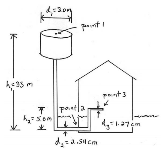
A cylindrical water tower of diameter 3.0 m supplies water to a house. The level of water in the water tower is 35 m above the point where the water enters the house through a pipe that has an inside diameter 5.1 cm. The intake pipe delivers water at a maximum rate of \(2.0 \times 10^{-3} \mathrm{m}^{3} \cdot \mathrm{s}^{-1}\). The pipe is connected to a narrower pipe leading to the second floor that has an inside diameter 2.5 cm . What is the pressure and speed of the water in the narrower pipe at a point that is a height 5.0 m above the level where the pipe enters the house?
Solution
We shall assume that the water is an ideal fluid and that the flow is a steady flow and that the level of water in the water tower is constantly maintained. Let’s choose three points, point 1 at the top of the water in the tower, point 2 where the water just enters the house, and point 3 in the narrow pipe at a height \(h_{2}=5.0 \mathrm{m}\) above the level where the pipe enters the house.
We begin by applying Bernoulli’s Equation to the flow from the water tower at point 1, to where the water just enters the house at point 2. Bernoulli’s equation (Equation (28.4.8)) tells us that
\[P_{1}+\rho g y_{1}+\frac{1}{2} \rho v_{1}^{2}=P_{2}+\rho g y_{2}+\frac{1}{2} \rho v_{2}^{2} \nonumber \]
We assume that the speed of the water at the top of the tower is negligibly small due to the fact that the water level in the tower is maintained at the same height and so we set \(v_{1}=0\). The pressure at point 2 is then
\[P_{2}=P_{1}+\rho g\left(y_{1}-y_{2}\right)-\frac{1}{2} \rho v_{2}^{2} \nonumber \]
In Equation (28.4.20) we use the value for the density of water
\[\rho=1.0 \times 10^{3} \mathrm{kg} \cdot \mathrm{m}^{-3}\), the change in height is \(\left(y_{1}-y_{2}\right)=35 \mathrm{m}, \nonumber \]
and the pressure at the top of the water tower is \begin{equation}P_{1}=1 \text{atm}\end{equation}. The rate R that the water flows at point 1 satisfies \(R=A_{1} v_{1}=\pi\left(d_{1} / 2\right)^{2} v_{1}\). Therefore, the speed of the water at point 1 is
\[v_{1}=\frac{R}{\pi\left(d_{1} / 2\right)^{2}}=\frac{2.0 \times 10^{-3} \mathrm{m}^{3} \cdot \mathrm{s}^{-1}}{\pi(1.5 \mathrm{m})^{2}}=2.8 \times 10^{-4} \mathrm{m} \cdot \mathrm{s}^{-1} \nonumber \]
which is negligibly small and so we are justified in setting \begin{equation}v_{1}=0\end{equation}. Similarly the speed of the water at point 2 is
\[v_{2}=\frac{R}{\pi\left(d_{2} / 2\right)^{2}}=\frac{2.0 \times 10^{-3} \mathrm{m}^{3} \cdot \mathrm{s}^{-1}}{\pi\left(2.5 \times 10^{-2} \mathrm{m}\right)^{2}}=1.0 \mathrm{m} \cdot \mathrm{s}^{-1} \nonumber \]
We can substitute Equation (28.4.21) into Equation (28.4.22), yielding
\[v_{2}=\left(d_{1}^{2} / d_{2}^{2}\right) v_{1} \nonumber \]
a result which we will shortly find useful. Therefore the pressure at point 2 is
\[\begin{array}{l}
P_{2}=1.01 \times 10^{5} \mathrm{Pa}+\left(1.0 \times 10^{3} \mathrm{kg} \cdot \mathrm{m}^{-3}\right)\left(9.8 \mathrm{m} \cdot \mathrm{s}^{-2}\right)(35 \mathrm{m})-\frac{1}{2}\left(1.0 \times 10^{3} \mathrm{kg} \cdot \mathrm{m}^{-3}\right)\left(1.0 \mathrm{m} \cdot \mathrm{s}^{-1}\right)^{2} \\
P_{2}=1.01 \times 10^{5} \mathrm{Pa}+3.43 \times 10^{5} \mathrm{Pa}-5.1 \times 10^{2} \mathrm{Pa}=4.4 \times 10^{5} \mathrm{Pa}
\end{array} \nonumber \]
The dominant contribution is due to the height difference between the top of the water tower and the pipe entering the house. The quantity \((1 / 2) \rho v_{2}^{2}\) is called the dynamic pressure due to the fact that the water is moving. The amount of reduction in pressure due to the fact that the water is moving at point 2 is given by
\[\frac{1}{2} \rho v_{2}^{2}=\frac{1}{2}\left(1.0 \times 10^{3} \mathrm{kg} \cdot \mathrm{m}^{-3}\right)\left(1.0 \mathrm{m} \cdot \mathrm{s}^{-1}\right)^{2}=5.1 \times 10^{3} \mathrm{Pa} \nonumber \]
which is much smaller than the contributions from the other two terms.
We now apply Bernoulli’s Equation to the points 2 and 3,
\[P_{2}+\frac{1}{2} \rho v_{2}^{2}+\rho g y_{2}=P_{3}+\frac{1}{2} \rho v_{3}^{2}+\rho g y_{3} \nonumber \]
Therefore the pressure at point 3 is
\[P_{3}=P_{2}+\frac{1}{2} \rho\left(v_{2}^{2}-v_{3}^{2}\right)+\rho g\left(y_{2}-y_{3}\right) \nonumber \]
The change in height \(y_{2}-y_{3}=-5.0 \mathrm{m}\). The speed of the water at point 3 is
\[v_{3}=\frac{R}{\pi\left(d_{3} / 2\right)^{2}}=\frac{2.0 \times 10^{-3} \mathrm{m}^{3} \cdot \mathrm{s}^{-1}}{\pi\left(1.27 \times 10^{-2} \mathrm{m}\right)^{2}}=3.9 \mathrm{m} \cdot \mathrm{s}^{-1} \nonumber \]
Then the pressure at point 3 is
\[\begin{array}{l}
P_{3}=\left(4.4 \times 10^{5} \mathrm{Pa}\right)+\frac{1}{2}\left(1.0 \times 10^{3} \mathrm{kg} \cdot \mathrm{m}^{-3}\right)\left(\left(1.0 \mathrm{m} \cdot \mathrm{s}^{-1}\right)^{2}-\left(3.9 \mathrm{m} \cdot \mathrm{s}^{-1}\right)^{2}\right) \\
-\left(1.0 \times 10^{3} \mathrm{kg} \cdot \mathrm{m}^{-3}\right)\left(9.8 \mathrm{m} \cdot \mathrm{s}^{-2}\right)(5.0 \mathrm{m}) \\
=\left(4.4 \times 10^{5} \mathrm{Pa}\right)-\left(7.1 \times 10^{3} \mathrm{Pa}\right)-4.9 \times 10^{4} \mathrm{Pa} \\
=3.8 \times 10^{5} \mathrm{Pa}
\end{array} \nonumber \]
Because the speed of the water at point 3 is much greater than at point 2, the dynamic pressure contribution at point 3 is much larger than at point 2.