9.3: Elliptically Polarized Plane Waves


- Last updated
- Jun 21, 2021
- Save as PDF

( \newcommand{\kernel}{\mathrm{null}\,}\)
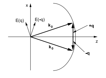
It may happen that two plane waves corresponding to the same frequency are propagating in the same direction, but they may have electric fields that are oriented in different directions and which may be shifted in phase relative to one another. For example, consider the plane waves of circular frequency ω and propagating along z as shown in Figure (9.2.3).
Let wave no.1 be polarized with its electric vector along the x-axis;
Ex=E1exp[i(kz−ωt)]
and
By=E1cexp[i(kz−ωt)].
Let wave no.2 be polarized with its electric vector along the y-axis:
Ey=E2exp[i(kz−ωt+ϕ)]
and
Bx=−E2cexp[i(kz−ωt+ϕ)].
Note that the fields in wave number(2) are shifted in phase by ϕ radians relative to the fields in wave number(1). Now make a diagram that displays the time variation of the total electric field at a fixed point in space; for simplicity, take z=0. There are a number of interesting cases:
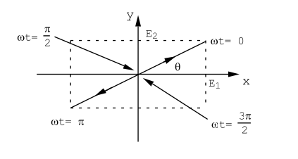
- Case(a). ϕ = 0. The two electric fields are in phase. This is an ordinary plane wave in which the electric vector is oriented at an angle with respect to the co-ordinate axes, Figure (9.3.4).
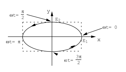
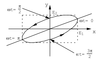
- Case(b). ϕ = π/2. The two electric fields are in quadrature i.e. they are 90◦ out of phase. The tip of the electric vector traces out an elliptical pattern as a function of time, Figure (9.3.5). The sense of rotation of the electric vector is such that a nut on a right handed screw thread would advance along the +z axis; this radiation is said to be right hand elliptically polarized. For the special case in which E1 = E2 the tip of the electric vector traces out a circle; such radiation is said to be right hand circularly polarized.
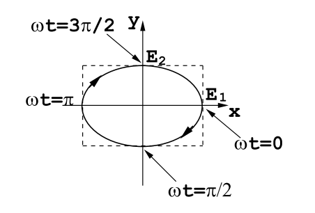
- Case(c). ϕ = 3π/2. In this case the electric fields are in quadrature, as for Case(b), but the sense of rotation of the electric vector is in the opposite direction, fig(9.3.6). This radiation is said to be left hand elliptically polarized. When E1 = E2 the radiation is left hand circularly polarized.
- Case(d). ϕ = π/4. The phase shift in this case is equal to 45◦ and is less
than 90◦ , Figure (9.3.7). The electric fields are given by
Ex=E1cosωt,Ey=E2√2(cosωt+sinωt).
The tip of the electric vector traces out an elliptical path as time goes on. The sense of the rotation is such that a nut on a right handed screw would advance along the positive z-axis; the radiation is right hand elliptically polarized. However, the principle axes of the ellipse are not parallel with the x,y co-ordinate axes. As the phase angle between the two electric vectors, ϕ, increases from zero, the ellipticity of the radiation increases and the principle axes of the ellipse rotate until they coincide with the co-ordinate axes at ϕ = π/2. Upon further increase in phase angle, the ellipticity decreases until the radiation becomes linearly polarized again for ϕ = π: the plane of polarization is rotated 90◦ relative to the plane of polarization illustrated in Figure (9.3.4). Further increases in the phase angle produces left hand elliptically polarized radiation.
The production of elliptically polarized radiation requires the superposition of two plane waves whose frequencies are identical, whose phases are correlated, and whose electric vectors are not co-linear. Such radiation is produced only by special sources. Visible radiation from a hot filament or from a hot plasma is usually unpolarized. The light emitted from such a source consists of a superposition of pulses each of which is quite short on a human time scale, ∼ 10−8 secs., but quite long compared with the period of the radiation, ∼ 10−14 to 10−15 secs. Each pulse is emitted from an atomic dipole oscillator that has been set into motion by thermal agitation. The pulses from the various atoms are uncorrelated in phase; moreover, the dipole moments on the individual atoms are oriented at random and so the orientation of the electric vector of the emitted light is also oriented at random. Unpolarized light consists of a collection of many pulses in which the orientation of the electric vector from pulse to pulse is random. A polaroid filter can be used to produce linearly polarized light from such an ensemble of randomly polarized pulses. It works because a polaroid filter preferentially absorbs light whose electric vector is parallel with a particular direction, i.e. the polaroid material exhibits anisotropic absorption. The light that gets through the filter consists of those pulses for which the electric vector is mainly oriented along the poorly absorbing axis of the crystals which make up a polaroid filter.
Visible radiation emitted from a gas laser source is usually plane polarized and coherent because the dipole moments on the radiating atoms in the laser plasma tube are parallel to one another and are locked in phase by the standing optical wave in the laser cavity. The whole ensemble of radiating atoms behaves like one enormous extended dipole source. The particular orientation of the electric field is determined by the Brewster windows that are used on the ends of the laser plasma tube. The optical gain provided by the laser plasma tube depends upon the orientation of the Brewster windows.
There exists a class of anisotropic materials such that the velocity of radiation depends upon the orientation of the electric vector relative to crystalline axes. Suitable thicknesses of such crystals can be used to introduce a controlled phase shift between two orthogonal components of the electric field. In that way it is possible to convert linearly polarized light to elliptically polarized light, and vice versa.