
12.1: Simple Transverse Electric Modes


- Last updated
- Jun 21, 2021
- Save as PDF

( \newcommand{\kernel}{\mathrm{null}\,}\)
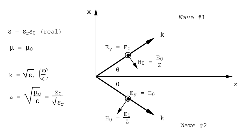
Consider two infinite plane waves of circular frequency ω oscillating in phase, and such that their propagation vectors lie in the x-z plane and make the angles θ with the z-axis: one wave has a positive x-component of wavevector, the other has a negative x-component of wave-vector, as illustrated in Figure 12.1.1. Explicit expressions for the electric and magnetic field components of these waves for the case in which the electric field in each wave has the same amplitude and is polarized along the y-direction are as follows:
Wave Number (1)
Ey1=E0exp(ixksinθ)exp(i[zkcosθ−ωt]),Hx1=−E0Zcosθexp(ixksinθ)exp(i[zkcosθ−ωt]),Hz1=E0Zsinθexp(ixksinθ)exp(i[zkcosθ−ωt]),
Wave Number (2)
Ey2=E0exp(−ixksinθ)exp(i[zkcosθ−ωt]),Hx2=−E0Zcosθexp(−ixksinθ)exp(i[zkcosθ−ωt]),Hz2=−E0Zsinθexp(−ixksinθ)exp(i[zkcosθ−ωt]).
In writing these equations it has been assumed that the waves are propagating in a medium characterized by a real dielectric constant ϵ=ϵrϵ0, and a magnetic permeability µ0. The wave-vector is k=√ϵr(ω/c), and the wave impedance is Z=√μ0/ϵ=Z0/√ϵr Ohms, where Z0 = 377 Ohms. The above fields satisfy Maxwell’s equations. One can now introduce two perfectly conducting infinite planes that lie parallel with the xz plane and which are separated by an arbitrary spacing, b. The plane waves of Figure 12.1.1 still satisfy Maxwell’s equations between the conducting surfaces: they also satisfy the required boundary conditions on the electric and magnetic fields. In the first place, there is only one electric field component, Ey, and it is normal to the conducting planes, consequently the tangential component of →E is zero on the perfectly conducting surfaces as is required. In the second place, the magnetic field components lie parallel with the conducting planes so that the normal component of →H is zero at the perfectly conducting planes as is required by the considerations discussed in Chpt.(10). The total electric field at any point in the space between the two conducting planes is given by
Ey=Ey1+Ey2,
or
Ey=2E0cos(xksinθ)exp(i[zkcosθ−ωt]).
The components of the magnetic field are given by
Hx=−2E0cosθZcos(xksinθ)exp(i[zkcosθ−ωt]),
and
Hz=+i2E0sinθZsin(xksinθ)exp(i[zkcosθ−ωt]).
Notice that Ey and Hx are both zero, independent of z, on the planes defined by (xk sin θ) = ±π/2, ±3π/2, ±5π/2, etc, i.e. on the planes
x=1ksinθ(±π2,±3π2, etc.).
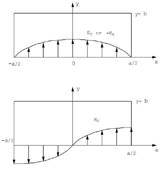
This means that the wave defined by Equations (???),(???), and (???) can propagate along the hollow rectangular pipe bounded by perfectly conducting planes spaced b apart along the y-direction, and spaced a apart along the x-direction where a= mπ/(k sin θ), and where m is an odd integer, and yet satisfy the boundary conditions imposed by the presence of the perfectly conducting surfaces. The distribution of the electric and magnetic fields across the section of the wave-guide formed by the intersection of the four conducting planes is shown in Figure 12.1.2 for the mode corresponding to k sin θ = π/a.
The width of the wave-guide along the x-direction, a, determines the propagation angle for waves that satisfy the boundary condition Ey = 0 on x=±a/2:
ksinθ=mπa=√ϵr(ωc)sinθ.
The component of the propagation vector parallel with the wave-guide axis, along z, is given by
kg=kcosθ=√ϵr(ωc)cosθ.
The sum of the squares of these two components must be equal to the square
of the wave-vector k, where k=√ϵrω/c:
k2=k2g+k2sin2θ=ϵr(ωc)2,
from which
k2g+m2(πa)2=ϵr(ωc)2,
where m is an odd integer.
The most important wave-guide mode is that for which m=1, the mode illustrated in Figure (12.1.2). In most applications the wave-guide is filled with air for which ϵr = 1. For this m=1 mode, and assuming that (\epsilon_{r}\)=1.0, the fields are given by
Ey=Acos(πxa)exp(i[kgz−ωt]),Hx=−AZ0(ckgω)cos(πxa)exp(i[kgz−ωt]),Hz=iAZ0(cπωa)sin(πxa)exp(i[kgz−ωt]),
where Z0=cμ0=√μ0/ϵ0. The mode of Equations (12.1.12), Figure 12.1.2, is called a transverse electric mode, or a TE mode, because the electric field has no component along the guide axis, i.e. no component along the direction of propagation of the wave-guide mode. Notice that the ratio Ey/Hx = ZG is independent of position inside the wave-guide; in particular, it is independent of position across the wave-guide cross-section. The magnetic field Hx is equivalent to a surface current density Jsy=Hx Amps/m (from curl(→H)=→Jf), and Ey has the units of Volts/m. The wave impedance ZG = Ey/Hx therefore has the units of Ohms: it plays a role for wave-guide problems that is similar to the role played by the characteristic impedance for transmission line problems. The analogy between transmission lines and wave-guides is discussed in a very clear manner in the article ” The Elements of Wave Propagation using the Impedance Concept” by H.G.Booker, Electrical Engineering Journal, volume 94, pages 171-202, 1947.
The Poynting vector, →S=→E×→H, associated with the TE10 mode, Equation (12.1.12), has two components:
Sx=EyHz,
and
Sz=−EyHx.
The time averaged value of Sx is zero; this corresponds to the fact that no energy, on average, is transported across the guide from one side to the other. There is a non-zero time average for the z-component of the Poynting vector corresponding to energy flow along the guide:
<Sz>=−12Real(EyH∗x)=12|A|2Z0(ckgω)cos2(πxa).
It is useful to integrate the time-averaged value of the Poynting vector over the cross-sectional area of the wave-guide in order to obtain the rate at which energy is carried past a particular section of the guide. A simple integration gives
b∫a/2−a/2<Sz>dx=ab4|A|2Z0(ckgω) Watts .
The time-averaged energy density associated with a wave-guide mode is given by
<W>=12Real(→E⋅→D∗2+→H⋅→B∗2),
or
<W>=14Real(ϵEyE∗y+μ0HxH∗x+μ0HzH∗z).
For the fundamental TE10 mode, Equations (12.1.12), one obtains
<W>=ϵ04|A|2cos2(πxa)+μ04|A|2Z20[(ckgω)2cos2(πxa)+(cπaω)2sin2(πxa)].
Integrate this energy density across a section of the guide in order to obtain the average energy per unit length of the wave-guide:
\[b∫a/2−a/2<W>dx=ab8|A|2(ϵ0+μ0Z20[(ckgω)2+(cπaω)2])=ab4ϵ0|A|2 Joules /m,
where we have used μ0/Z20=ϵ0, and for a waveguide filled with air
(ckgω)2+(cπaω)2=ϵr=1.0.
The velocity with which energy is transported down the guide is called the group velocity, vg. The group velocity must have a value such that its product with the energy density per unit length of guide, Equation (12.1.21), gives the rate at which energy is transported past a wave-guide section, Equation (???): i.e.
vgabϵ04|A|2=ab4|A|2Z0(ckgω).
Thus
vg=c(ckgω)m/sec.
It is easy to verify by direct differentiation of Equation (???) that this velocity is also given by the relation
vg=∂ω∂kg.
Equation (???) is valid for an arbitrary relative dielectric constant: from (???)
vg=cϵr(ckgω).
The phase velocity, vphase, on the other hand is obtained from the condition
kgz−ωt= constant .
That is z must increase at the rate
vphase=dzdt=ωkg
in order to remain on a crest as the wave propagates along the guide. As the guide wave-vector, kg, approaches zero the phase velocity may become very large- much larger than the velocity of light in vacuum. This occurs because the phase velocity measures the rate of propagation down the guide of two intersecting wave fronts as these waves bounce back and forth across the guide ( see Figure (12.1.3)). This intersection velocity clearly becomes infinitely
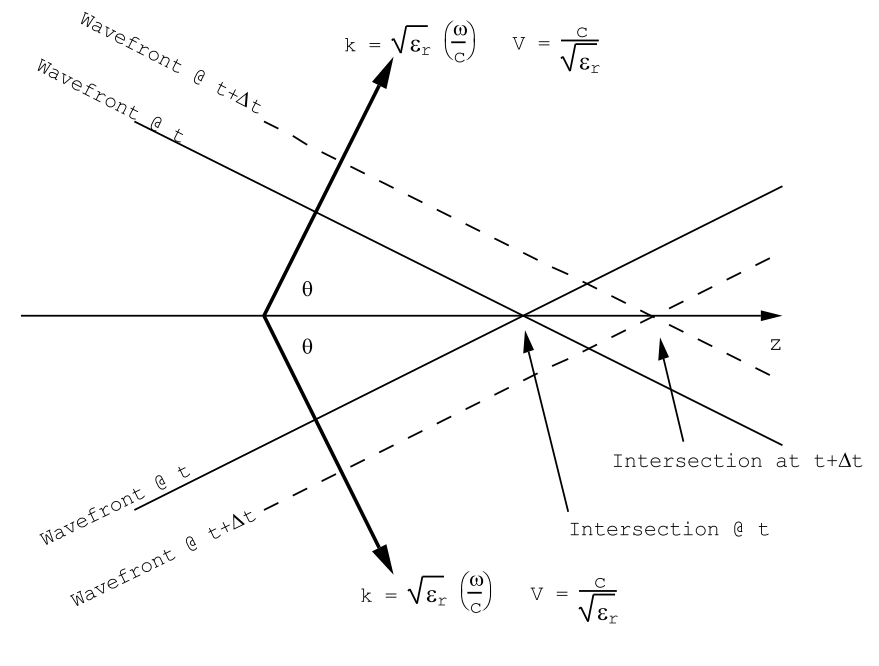
large in the limit as the wavefronts become parallel with the guide axis, i.e. in the limit as the guide wave-number, kg, goes to zero. The velocity of energy transport down the guide, the group velocity, goes to zero as θ approaches π/2, the condition corresponding to waves that simply bounce forth and back along the x-direction between the perfectly conducting planes at x = ±a/2. The group velocity, the velocity with which information can be transmitted down the guide, is always less than the velocity of light in vacuum.
The frequency at which the group velocity goes to zero can be calculated from Equation (???) by setting kg = 0, since the group velocity is proportional to kg from (???):
ωm=cπa√ϵr.
The wave-guide is a high pass filter that will transmit energy for frequencies larger than the cut-off frequency ωm. For ϵr = 1 and a=1 cm, the cut-off frequency is ωm = 9.42 × 10¹⁰ radians/sec. corresponding to a frequency of f=15 GHz.
It should be clear from the above construction that Equations (12.1.12) represents the solution of Maxwell’s equations for the TE10 mode that carries energy in the positive z-direction. The TE10 mode that carries energy in the negative z-direction is described by
Ey=Bcos(πxa)exp(−i[kgz+ωt]),Hx=BZ0(ckgω)cos(πxa)exp(−i[kgz+ωt]),Hz=iBZ0(cπaω)sin(πxa)exp(−i[kgz+ωt]),
where B is an arbitrary amplitude (NOT the magnetic field!).
In order to answer the question of what happens if the frequency is less than the cut-off frequency, ωm, it is best to start from Maxwell’s equations. Consider the case for which there is only a y-component of electric field. From
curl(→E)=−∂→B∂t=iωμ0→H,
for a time dependence ∼ exp (−iωt), and for the permeability of free space, one obtains
iωμ0Hx=−∂Ey∂z,
and
iωμ0Hz=∂Ey∂x.
From
curl(→H)=∂→D∂t=−iωϵ→E
one obtains
∂Hx∂z−∂Hz∂x=−iωϵEy.
The above equations can be combined to give a single second order equation for Ey:
∂2Ey∂x2+∂2Ey∂z2=−ϵr(ωc)2Ey.
For an electric field having the form
Ey=Acos(πxa)exp(i[kgz−ωt])
it follows that
(πa)2+k2g=ϵr(ωc)2,
or
k2g=ϵr(ωc)2−(πa)2.
For a frequency less than the cut-off frequency corresponding to ωm = cπ/a√ϵr the square of the wave-vector kg becomes negative and therefore its square root becomes pure imaginary. A pure imaginary wave-vector
kg=±iα,
where α is a real number, corresponds to a disturbance that decays away exponentially along the guide either to the right or to the left. For example, kg = +iα gives a disturbance of the form
Ey=Acos(πxa)exp(−αz)exp(−iωt),
with magnetic field components (from Equation (???) and Equation (???))
Hx=−i1Z0(cαω)Acos(πxa)exp(−αz)exp(−iωt),
and
Hz=i1Z0(cπωa)Asin(πxa)exp(−αz)exp(−iωt),
Using these components, it is easy to show that the time-averaged z-component of the Poynting vector, Sz = −EyHx, is exactly equal to zero. The average energy density stored in the fields is not zero:
<WE>=ϵ4|A|2cos2(πxa)exp(−2αz),
and
<WB>=μ04|A|2Z20exp(−2αz)((cαω)2cos2(πxa)+(cπωa)2sin2(πxa)).
These expressions correspond to the energy density stored in the electric field, ( ???), and to the energy density stored in the magnetic field, ( ???). If a source of energy oscillating at a frequency less than the cut-off frequency is introduced into a wave-guide at some point, the resulting electromagnetic fields will remain localized around the source, and the effective load on the source will be purely reactive for a wave-guide whose walls are perfectly conducting. In the case of a real guide whose walls have some finite resistivity, the load on a source oscillating at a frequency which is less than the cut-off frequency will appear to be partly resistive but mainly reactive.