
1.10: Reflection and Transmission at an Interface


- Last updated
- Sep 16, 2022
- Save as PDF

( \newcommand{\kernel}{\mathrm{null}\,}\)
When an electromagnetic field is incident on an interface between different media, the field is partially reflected and partially transmitted. An important special case is that of a monochromatic plane wave which is incident on a planar interface as in Figure 1.10.2.
Let the interface be the plane z=0 between materials in z<0 and z>0 with permittivities Ei and Et, respectively. We first assume that the materials are lossless, i.e. that the permittivities are real. The plane wave is incident from medium z<0 and the incident electromagnetic field is given by:
εi(r,t)=Re[εi(r)e−iωt]=Re[Aiei(ki·r−ωt)]
and
Hi(r,t)=Re[Hi(r)e−iωt]=Re[kiωµ0×Aiei(ki·r−ωt)]
where ki = kixx + kiyy + kizz, with
k_{z}^i=(k_{0}^2E_{i} − (k_{x}^i)^2 − (k_{y}^i)^2)^{1/2}. \nonumber
Because the time dependence is given by \exp(−iωt) with ω > 0 and the incident wave propagates in the positive z-direction, the positive square root is chosen for kiz . Part of the incident field is reflected into z < 0 and part is transmitted into z > 0. The reflected field is written as
ε^r(r, t) = Re [ ε^r(r)e^{−iωt}] = Re [ A^re^{i(k^{r}·r−ωt)}] , \nonumber
H^r(r, t) = Re [ H^r(r)e^{−iωt}] = Re [ \dfrac{k^r}{ωµ_{0}} × A^re^{i(k^{r}·r−ωt)}] , \nonumber
where kr = krxx + kryy + krzz, with
k_{z}^r=(k_{0}^2E_{i} − (k_{x}^r)^2 − (k_{y}^r)^2)^{1/2}, \nonumber
where the minus sign is chosen because the reflected wave propagates in the negative z-direction. The transmitted field is for z > 0
ε^t(r, t) = Re [ ε^t(r)e^{−iωt}] = Re [ A^te^{i(k^{t}·r−ωt)}] , \nonumber
H^t(r, t) = Re [ H^t(r)e^{−iωt}] = Re [ \dfrac{k^t}{ωµ_{0}} × A^te^{i(k^{t}·r−ωt)}] , \nonumber
where kt = ktxx + ktyy + ktzz, with
k_{z}^t=(k_{0}^2E_{i} − (k_{x}^t)^2 − (k_{y}^t)^2)^{1/2}. \nonumber
Our aim is to determine Ar and At for given Ai.
1.9.1 Boundary Conditions at an Interface
There exist conditions for the continuity of the tangential and the normal components of both the electric and magnetic fields at an interface between different media. The boundary conditions for the tangential components follow from the Maxwell equations that contain the curl-operator, i.e. (1.6.2) and (1.6.3). There holds for the interface z = 0 with the incident, reflected and transmitted plane waves introduced above:
\hat{z} × (E^i + E^r ) = \hat{z} × E^t, \nonumber
\hat{z} × (H^i + H^r ) = \hat{z} × H^t, \nonumber
where z is the unit normal on the interface. This means that the tangential components of the total electric and total magnetic field are continuous across the interface, or explicitly:
E_{x}^i(x, y, 0) + E_{x}^r(x, y, 0) = E_{x}^t(x, y, 0), \nonumber
E_{y}^i(x, y, 0) + E_{y}^r(x, y, 0) = E_{y}^t(x, y, 0), \nonumber
and similarly for the magnetic field.
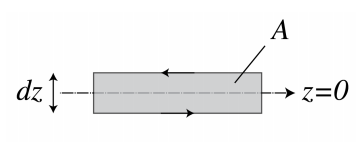
We will only demonstrate the continuity of the tangential components for the electric field. By choosing a closed loop in the (x, z)-plane which is intersected by the interface z = 0 as shown in Figure \PageIndex{1}, and integrating the y-component of Faraday’s Law (1.3.12) for the total electromagnetic field over the area A bounded by the loop L, we obtain:
-µ_{0}\dfrac{d}{dt}\iint\limits_{A} \hat{y}H\, dA=\iint\limits_{A} \hat{y}∇ × ε\, dA=\oint\limits_{L} ε\, dl \nonumber
where in the last step we used Stokes’ theorem with the direction of integration over the loop given by that of the direction of rotation of screw driver when it moves in the direction of the normal y. In words: the rate of change of the magnetic flux through the surface A is equal to the integral of the tangential electric field over the bounding closed loop L.
By taking the limit dz → 0, the surface integral and the integrals over the vertical parts of the loop vanish and there remain only the integrals of the tangential electric field over the horizontal parts of the loop on both sides of the interface z = 0. Since these integrals are traversed in opposite directions and the lengths of these parts are the same and arbitrary, we conclude for the loop as shown in Figure \PageIndex{1} that
lim_{z↑0} ε_{x}(x, y, z, t) = lim_{z↓0} ε_{x}(x, y, z, t), \nonumber
where ε is the total electric field, i.e. it is equal to the sum of the incident and the reflected field for z < 0, and equal to the transmitted field in z > 0. By choosing the closed loop in the (y, z)-plane instead of the (x, z)-plane one finds similarly that the y-component of the electric field is continuous. The continuity of the tangential components of the magnetic field are derived in a similar manner.
Our derivation holds for electromagnetic fields of arbitrary time dependence. Furthermore, the derivation used above for the planar interface z = 0 can easily be generalized for curved surfaces. Therefore we conclude:
The tangential electric and magnetic field components are continuous across any interface.
By integrating Maxwell’s equations that contain the div-operator (1.3.14), (1.3.15) over a pill box with height dz and top and bottom surfaces on either side and parallel to the interface, and considering the limit dz → 0, we find continuity relations for the normal components of the fields:
lim_{z↑0} E_{i}\hat{z}ε_{x}(x, y, z, t) = lim_{z↓0} E_{t}\hat{z}εx(x, y, z, t), \nonumber
lim_{z↑0} H_{x}(x, y, z, t) = lim_{z↓0} H_{x}(x, y, z, t), \nonumber
The normal components of Eε and H are continuous across an interface.
Since all derived boundary conditions hold for all times t, it follows that for timeharmonic fields they also hold for the complex fields. Hence (\PageIndex{10}) and (\PageIndex{11}) hold and similarly we find that the normal components of Eε and H are continuous.
1.9.2 Snell’s Law
By substituting the complex electric fields derived from (\PageIndex{1}), (\PageIndex{4}) and (\PageIndex{7}) into equation (\PageIndex{10}), we get
\hat{z} × [A^ie^{i(k_{x}^{i}·x+k_{y}^{i}·y)}+A^re^{i(k_{x}^{r}·x+k_{y}^{r}·y)}]=\hat{z} × A^te^{i(k_{x}^{t}·x+k_{y}^{t}·y)}, \nonumber
Since this equation must be satisfied for all points (x, y), it follows that
k_{x}^{i}=k_{x}^{r}=k_{x}^{t}, \nonumber
k_{y}^{i}=k_{y}^{r}=k_{y}^{t}, \nonumber
Hence, the tangential components of the wave vectors of the incident, reflected and transmitted waves are identical. In fact, if (\PageIndex{19}) would not hold, then by keeping y fixed, the exponential functions in (\PageIndex{18}) would not all have the same periodicity as functions of x and then (\PageIndex{18}) could never be satisfied for all x. The same argument with x kept fixed leads to the conclusion (\PageIndex{20}).
Without restricting the generality, we will from now on assume that the coordinate system is chosen such that
k_{y}^{i}=k_{y}^{r}=k_{y}^{t}=0. \nonumber
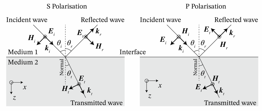
The plane through the incident wave vector and the normal to the interface is called the plane of incidence. Hence in the case of (\PageIndex{21}) the plane of incidence is the (x, z)-plane.
Since the length of the wave vectors ki and kr is k0ni, with k0 the wave number in vacuum and ni = (Ei/E0)1/2 the refractive index, and since the length of kt is k0nt , with nt = (Et/E0)1/2, it follows from (\PageIndex{19})
sin θ_{i} = \dfrac{k_{x}^{i}}{k_{0}n_{i}}=\dfrac{k_{x}^{r}}{k_{0}n_{r}}=sin θ_{r}, \nonumber
and
n_{i}sin θ_{i} = \dfrac{k_{x}^{i}}{k_{0}}=\dfrac{k_{x}^{t}}{k_{0}}=n_{t}sin θ_{t}, \nonumber
where the angles are as in Figure \PageIndex{2}. Hence,
θ_{i} = θ_{r}, angle\space of\space reflection = angle\space of\space incidence, \nonumber
n_{i}sin θ_{i} =n_{t}sin θ_{t},Snell’s\space Law . \nonumber
Snell’s Law implies that when the angle of incidence θi increases, the angle of transmission increases as well. If the medium in z < 0 is air with refractive index ni = 1 and the other medium is glass with refractive index nt = 1.5, then the maximum angle of transmission occurs when θi = 90o with
θ_{t,max} = arcsin(n_{i}/n_{t}) = 41.8^o. \nonumber
In case the light is incident from glass, i.e. ni = 1.5 and nt = 1.0, the angle of incidence θi cannot be larger than 41.8o because otherwise there is no real solution for θt . It turns out that when θi > 41.8o , the wave is totally reflected and there is no propagating transmitted wave in air. As explained in Section 1.9.5, this does however not mean that there is no field in z > 0. In fact there is a non-propagating so-called evanescent wave in z > 0. The angle θi,crit = 41.8o is called the critical angle of total internal reflection. It exists only if a wave is incident from a medium with larger refractive index on a medium with lower refractive index (nt < ni). The critical angle is independent of the polarisation of the incident wave.
1.9.3 Fresnel Coefficients
Because of (\PageIndex{19}) and (\PageIndex{21}), we write kx = kix = krx = ktx and therefore kiz = (k20Ei − k2x)1/2 = −krz and ktz = (k20Et − k2x)1/2 . Hence,
k^i = k_{x}\hat{x} + k^i_{z}\hat{z}, k^r = k_{x}\hat{x} − k^i_{z}\hat{z}, \nonumber
and
k^t =k_{x}\hat{x} − k^t_{z}\hat{z}, \nonumber
According to (1.6.11), for the incident, reflected and transmitted plane waves there must hold:
A^i · k^i = A^r · k^r = A^t · k^t = 0. \nonumber
We choose an orthonormal basis perpendicular to ki with unit vectors:
\hat{s}= \hat{y} , \hat{p}^i=\dfrac{1}{|k^i|}(-k_{z}^i\hat{x}+k_{x}\hat{z}), \nonumber
where
|k^i|= (k^i · (k^i)^*)^{1/2}=(k_{x}^2 · |k_{z}^i|^2)^{1/2}, \nonumber
and where in writing the complex conjugate we anticipate the case the kiz is complex, which may happen for example when Ei is complex (a case that has been excluded so far but which later will be considered) or in the case of evanescent waves discussed in Section 1.9.5. Note that when kiz is real, |ki| = (k2x + (kiz)2)1/2 = k0ni . It is easy to see that the basis (\PageIndex{30}) is orthonormal in the space of two-dimensional complex vectors and that s · ki = pi · ki = 0. The vector s is perpendicular to the plane of incidence, therefore the electric field component in this direction is polarised perpendicular to the plane of incidence and is called s-polarised ("Senkrecht" in German). The other basis vector pi is (for real ki ) parallel to the plane of incidence and when the electric component in this direction is called p-polarised. The complex vector Ai can be expanded on this basis:
A^i = A^i_{s} \hat{y} + A^i_{p} \hat{p}^i. \nonumber
Since
k^i × \hat{y} = |k^i|\hat{p}^i, k^i × \hat{p}^i =-\dfrac{k^2_{0}E_{i}}{|k^i|}\hat{y}, \nonumber
it follows that the electric and magnetic field of the incident plane wave can be written as
E^i(r) =(A^i_{s} \hat{y} + A^i_{p} \hat{p}^i)e^{ik^i·r}, \nonumber
H^i(r) = (\dfrac{|k^i|}{ωµ_{0}}A^i_{s}\hat{p}^i-\dfrac{ωE_{0}E_{i}}{|k^i|}A^i_{p}\hat{y})e^{ik^i·r}. \nonumber
The reflected field is expanded on the basis y and pr with
\hat{p}^r=-\dfrac{1}{|k^i|}(k^i_{z}\hat{x}+k_{x}\hat{z}). \nonumber
The sign in front of the unit vector pr is chosen such that that its x-component is the same as that of pi . Since
k^r × \hat{y} = -|k^i|\hat{p}^r, k^r × \hat{p}^r =\dfrac{k^2_{0}E_{i}}{|k^i|}\hat{y}, \nonumber
it follows that
E^r(r) =(A^r_{s} \hat{y} + A^r_{p} \hat{p}^r)e^{ik^r·r}, \nonumber
H^r(r) = (-\dfrac{|k^i|}{ωµ_{0}}A^r_{s}\hat{p}^r+\dfrac{ωE_{0}E_{i}}{|k^i|}A^r_{p}\hat{y})e^{ik^r·r}, \nonumber
where we used that kr · kr = k02ni2 and |kr| = (kx2 + |kzr|2)1/2 = (kx2 + |kzi|2)1/2 = |ki|. For the transmitted plane wave we use the basis y and pt with
\hat{p}^t=\dfrac{1}{|k^t|}(-k^t_{z}\hat{x}+k_{x}\hat{z}), \nonumber
where pt is chosen such that the x-component of pt has the same sign as the x-component of pi. Since
k^t × \hat{y} = |k^t|\hat{p}^t, k^t × \hat{p}^t =\dfrac{k^2_{0}E_{t}}{|k^t|}\hat{y}, \nonumber
we get
E^t(r) =(A^t_{s} \hat{y} + A^t_{p} \hat{p}^t)e^{ik^t·r}, \nonumber
H^t(r) = (\dfrac{|k^t|}{ωµ_{0}}A^t_{s}\hat{p}^t-\dfrac{ωE_{0}E_{i}}{|k^t|}A^t_{p}\hat{y})e^{ik^t·r}, \nonumber
We now consider an s-polarised incident plane wave, i.e. Api= 0. We will show that all boundary conditions can be satisfied by Apr = Apt = 0 and by appropriately expressing Asr and Ast in terms of Asi . This implies that if the incident plane wave is s-polarised, the reflected and transmitted waves are s-polarised as well. For s-polarisation, the electric field has only a y-component and this component is tangential to the interface z = 0. This leads to the condition
A^i_{s}+A^r_{s}=A^t_{s}. \nonumber
The only tangential component of the magnetic field is the x-component and requiring it to be continuous for z = 0 leads to
-k^i_{z}A^i_{s}+k^i_{z}A^r_{s}=-k^t_{z}A^t_{s}. \nonumber
Solving (\PageIndex{44}), (\PageIndex{45}) for Asr and Ast gives the following formula for the reflection and transmission coefficients:
r_{s}=\dfrac{ A^r_{s} }{ A^i_{s} }=\dfrac{ k^i_{z} -k^t_{z} }{k^i_{z} +A^t_{z} }, \nonumber
t_{s}=\dfrac{ A^t_{s} }{ A^i_{s} }=\dfrac{ 2k^i_{z} }{k^i_{z} +A^t_{z} }. \nonumber
Only the magnetic field has a z-component and it easy to verify that Hzi + Hzr = Hz for z = 0.
By looking at the case of a p-polarised incident wave: Asi = 0, we see that the expression for the magnetic field in the p-polarised case become similar (except for the chosen signs) to that of the electric field for s-polarisation and conversely. Enforcing the continuity of the tangential components at z = 0 gives for p-polarisation:
r_{p}=\dfrac{ A^r_{p} }{ A^i_{p} }=-\dfrac{ \dfrac{k^i_{p}}{E_{i}} -\dfrac{k^t_{p}}{E_{t}}}{\dfrac{k^i_{p}}{E_{i}} +\dfrac{k^t_{p}}{E_{t}}} , \nonumber
t_{p}=\dfrac{ A^t_{p} }{ A^i_{p} }=\dfrac{ 2 \dfrac{k^i_{p}}{E_{i}} }{ \dfrac{k^i_{p}}{E_{i}} +\dfrac{k^t_{p}}{E_{t}} }. \nonumber
It is easy to verify that Ez is the only normal component and that ei(Ezi + Ezr ) = etEzt for z = 0.
The reflection and transmission coefficients rs, rp, ts and tp are called Fresnel coefficients. As follows from the derivation, there is no cross talk between s- and p-polarised plane waves incident on a planar interface. A generally polarised incident plane wave can always be written as a linear combination of s- and a p-polarised incident plane waves. Because in general rs ≠ rp and ts ≠ tp , it follows that the reflected and transmitted fields are also linear combinations of s- and p-polarised fields, but with different coefficients (weights) of these two fundamental polarisation states than for the incident wave.
Remarks.
1. In the derivation of the Fresnel coefficients the continuity of the normal field components was not used and was automatically satisfied. The reason is that the electromagnetic fields of the plane waves where chosen to be perpendicular to the wave vectors. This implies that the divergence of Eε and of H vanishes which in turns implies that the normal components are automatically continuous across the the interface.
2. When kiz and ktz are both real, we have |ki| = k0ni and |kt| = k0nt and the Fresnel coefficients can be expressed in the angles θi, θr and θt and the refractive indices ni = Ei1/2/E0 and nt = (Et/E0)1/2. Because kzi = k0ni cos θi and kzt = k0nt cos θt , we find
r_{s}=\dfrac{n_{i}cosθ_{i}-n_{t}cosθ_{t}}{n_{i}cosθ_{i}+n_{t}cosθ_{t}}=-\dfrac{sin(θ_{i}-θ_{t})}{sin(θ_{i}+θ_{t})}, \nonumber
t_{s}=\dfrac{2n_{i}cosθ_{i}}{n_{i}cosθ_{i}+n_{t}cosθ_{t}}=\dfrac{2cosθ_{i}sinθ_{t}}{sin(θ_{i}+θ_{t})}, \nonumber
and
r_{p}=-\dfrac{ \dfrac{cosθ_{i}}{n_{i}}- \dfrac{cosθ_{t}}{n_{t}}}{ \dfrac{cosθ_{i}}{n_{i}}- \dfrac{cosθ_{t}}{n_{t}} }=-\dfrac{tan(θ_{i}-θ_{t})}{tan(θ_{i}+θ_{t})}, \nonumber
t_{p}=\dfrac{\dfrac{2cosθ_{i}}{n_{i}}}{ \dfrac{cosθ_{i}}{n_{i}}+ \dfrac{cosθ_{t}}{n_{t}} }=-\dfrac{ 2cosθ_{i}sinθ_{t} }{tan(θ_{i}+θ_{t})}. \nonumber
To obtain the expressions at the far right in (\PageIndex{50}), (\PageIndex{51}), (\PageIndex{52}) and (\PageIndex{53}) Snell’s Law has been used.
3. The advantage of the expressions (\PageIndex{46}), (\PageIndex{47}), (\PageIndex{48}), (\PageIndex{49}) in terms of the wave vector components kiz and ktz is, that they also apply when kzi and/or kzt are complex. This happens for example when there is absorption in z < 0 or in z > 0 or both, or when Ei > Et and the incident angle is above the critical angle, due to which kzt is purely imaginary (see Section 1.9.5).
1.9.4 Properties of the Fresnel Coefficients
For normal incidence: θi = 0, Snell’s Law implies: θt = 0. Hence, (\PageIndex{50}), (\PageIndex{52}) give:
r_{s}(θ_{i}=0)=r_{p}(θ_{i}=0)=\dfrac{n_{i}-n_{t}}{n_{i}+n_{t}}, \nonumber
Is is seen that for normal incidence rp = rs, as expected. Note however that if we would not have defined pr such that its tangential component is the same as that of pi , the two reflection coefficients would have the opposite sign for normal incidence (as is the case in some books). If the incident medium is air and the other medium is glass (ni = 1.0, nt = 1.5), we get
r_{s}(θ_{i}=0)=r_{p}(θ_{i}=0)=-0.2, \nonumber
and since the flow of energy is proportional to the square of the field, it follows that 4% of normal incident light is reflected by the glass. Hence a lens of glass without anti-reflection coating reflects approximately 4% of the light at normal incidence. The transmission coefficient for normal incidence is:
t_{s}(θ_{i}=0)=r_{p}(θ_{i}=0)=\dfrac{2n_{i}}{n_{i}+n_{t}}, \nonumber
which for air-glass becomes 0.8.
Remark. Energy conservation requires that the normal component < Sz > of the time-averaged energy flux through the interface is continuous. By using the formula for the time-averaged Poynting vector of a plane wave (1.8.8), it can be verified that the Fresnel coefficients are such that the energy flux is indeed continuous.
It follows from Snell’s Law (\PageIndex{25}) that sin θt = (ni/nt) sin θi . Hence θt monotonically increases with θi and therefore there exists some θi such that
θ_{i}+θ_{t}=90^o. \nonumber
For this particular angle of incidence, the denominator of (\PageIndex{52}) is infinite and hence rp = 0, i.e. the p-polarised wave is not reflected at all. This angle of incidence is called the Brewster angle θB . It is easy to see from (\PageIndex{50}) that the reflection is never zero for s-polarisation.
If unpolarised light is incident at the Brewster angle, the reflected light will be purely s-polarised.
Since at the Brewster angle s-polarised light is only partially reflected and the rest is transmitted, the transmitted light at the Brewster angle is a mixture of s- and p-polarisation. We have θt = 90o − θi , hence sin θt = cos θi and by Snell’s Law (writing θi = θB):
tan(θ_{B})=\dfrac{n_{t}}{n_{i}}. \nonumber
We see that there is always a solution, independent of whether the wave is incident from the material with the smallest or largest refractive index. For the air-glass interface we have θB = 56.3o and θt = 33.7o . By (\PageIndex{50}):
r_{s}(θ_{B}=56.3^o)=-0.38 \nonumber
so that (0.38)2/2 = 0.07, or 7 % of the unpolarised light is reflected as purely s-polarised light at the air glass interface. For a wave incident from glass, θB = 33.7o.
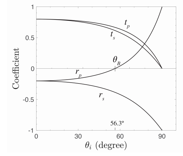
In Figure \PageIndex{3} the reflection and transmission coefficients of s- and p-polarised waves are shown as a function of the angle of incidence for the case of incidence from air to glass. There is no critical angle of total reflection in this case. The Brewster angle is indicated. It is seen that the reflection coefficients decrease from the values −0.2 for θi = 0o to -1 for θi = 90o . The transmission coefficients monotonically decrease to 0 at θi = 90o.
Figure \PageIndex{3} shows the Fresnel coefficients when the wave is incident from glass to air. The critical angle is θi,crit = 41.8o as derived earlier. At the angle of total internal reflection the absolute values of the reflection coefficients are identical to 1. There is again an angle where the reflection of p-polarised light is zero θB = 33.7o.
Depending on the refractive indices and the angle of incidence, the reflection coefficients can be negative. The reflected electric field then has an additional π phase shift compared to the incident wave. In contrast, (provided that the materials are lossless), the transmitted field is always in phase with the incident field, i.e. the transmission coefficients are always positive.
1.9.5 Total Internal Reflection and Evanescent Waves
We return to the case of a wave incident from glass to air, i.e. ni = 1.5 and nt = 1. As has been explained, there is then a critical angle, given by sinθi,crit=nt/ni.
This is equivalent to
k_{x}^t=k_{0}n_{i}sinθ_{i,crit}=k_{0}n_{t} \nonumber
The wave vector kt = kxtx + kztz in z > 0 satisfies:
(k_{x}^t)^2+(k_{z}^t)^2=k_{0}^2n_{t}^2. \nonumber
Because of (\PageIndex{60}), we have at the critical angle
k_{z}^t=0. \nonumber
For angles of incidence above the critical angle we have: kxt > k0nt and it follows from (\PageIndex{61}) that (kzt)2 = k02nt2 − (kxt)2 < 0, hence kzt is imaginary:
k_{z}^t=±(k_{0}^2n_{t}^2-(k_{x}^t)^2)^{1/2}=±i((k_{x}^t)^2-k_{0}^2)^{1/2}, \nonumber
where the last square root is a positive real number. It can be shown that above the critical angle the reflection coefficients are complex numbers with modulus 1: |rs| = |rp| = 1. This implies that the reflected intensity is identical to the incident intensity, while at the same time the transmission coefficients are not zero! For example, for s-polarisation we have according to (\PageIndex{46}), (\PageIndex{47}):
t_{s}=1+r_{s}≠0, \nonumber
because rs ≠ −1 (although |rs| = 1). Therefore there is an electric field in z > 0, given by
E(x,z)e^{-iωt}=t_{s}e^{ik_{x}^tx+ik_{z}^tz-iωt}\hat{y}=t_{s}e^{i(k_{x}^tx-ωt)}e^{-z((k_{x}^t)^2-k_{0}^2n_{t}^2)^{1/2}}\hat{y},z>0, \nonumber
where we have chosen the + sign in (\PageIndex{63}) to prevent the field from blowing up for z → ∞. Since kxt is real, the wave propagates in the x-direction. In the z-direction, however, the wave is not propagating. Its amplitude decreases exponentially as a function of distance z to the interface and therefore the wave is confined to a thin layer adjacent to the interface. Such a wave is called an evanescent wave. One can compute the Poynting vector of the evanescent wave and find that this vector is parallel to the interface. Hence, the flow of energy of an evanescent wave propagates parallel to the interface namely in the direction in which ktx is positive
Hence no energy is transported away from the interface into the air region. We shall return to evanescent waves in the chapter on diffraction theory.
1. Youtube video - 8.03 - Lect 18 - Index of Refraction, Reflection, Fresnel Equations, Brewster Angle - Lecture by Walter Lewin
2. MIT OCW - Reflection at The Air-glass Boundary: demonstration of reflection of polarised light and the Brewster angle.