1.5: Reflection and Refraction
- Page ID
- 7070

\( \newcommand{\vecs}[1]{\overset { \scriptstyle \rightharpoonup} {\mathbf{#1}} } \)
\( \newcommand{\vecd}[1]{\overset{-\!-\!\rightharpoonup}{\vphantom{a}\smash {#1}}} \)
\( \newcommand{\dsum}{\displaystyle\sum\limits} \)
\( \newcommand{\dint}{\displaystyle\int\limits} \)
\( \newcommand{\dlim}{\displaystyle\lim\limits} \)
\( \newcommand{\id}{\mathrm{id}}\) \( \newcommand{\Span}{\mathrm{span}}\)
( \newcommand{\kernel}{\mathrm{null}\,}\) \( \newcommand{\range}{\mathrm{range}\,}\)
\( \newcommand{\RealPart}{\mathrm{Re}}\) \( \newcommand{\ImaginaryPart}{\mathrm{Im}}\)
\( \newcommand{\Argument}{\mathrm{Arg}}\) \( \newcommand{\norm}[1]{\| #1 \|}\)
\( \newcommand{\inner}[2]{\langle #1, #2 \rangle}\)
\( \newcommand{\Span}{\mathrm{span}}\)
\( \newcommand{\id}{\mathrm{id}}\)
\( \newcommand{\Span}{\mathrm{span}}\)
\( \newcommand{\kernel}{\mathrm{null}\,}\)
\( \newcommand{\range}{\mathrm{range}\,}\)
\( \newcommand{\RealPart}{\mathrm{Re}}\)
\( \newcommand{\ImaginaryPart}{\mathrm{Im}}\)
\( \newcommand{\Argument}{\mathrm{Arg}}\)
\( \newcommand{\norm}[1]{\| #1 \|}\)
\( \newcommand{\inner}[2]{\langle #1, #2 \rangle}\)
\( \newcommand{\Span}{\mathrm{span}}\) \( \newcommand{\AA}{\unicode[.8,0]{x212B}}\)
\( \newcommand{\vectorA}[1]{\vec{#1}} % arrow\)
\( \newcommand{\vectorAt}[1]{\vec{\text{#1}}} % arrow\)
\( \newcommand{\vectorB}[1]{\overset { \scriptstyle \rightharpoonup} {\mathbf{#1}} } \)
\( \newcommand{\vectorC}[1]{\textbf{#1}} \)
\( \newcommand{\vectorD}[1]{\overrightarrow{#1}} \)
\( \newcommand{\vectorDt}[1]{\overrightarrow{\text{#1}}} \)
\( \newcommand{\vectE}[1]{\overset{-\!-\!\rightharpoonup}{\vphantom{a}\smash{\mathbf {#1}}}} \)
\( \newcommand{\vecs}[1]{\overset { \scriptstyle \rightharpoonup} {\mathbf{#1}} } \)
\(\newcommand{\longvect}{\overrightarrow}\)
\( \newcommand{\vecd}[1]{\overset{-\!-\!\rightharpoonup}{\vphantom{a}\smash {#1}}} \)
\(\newcommand{\avec}{\mathbf a}\) \(\newcommand{\bvec}{\mathbf b}\) \(\newcommand{\cvec}{\mathbf c}\) \(\newcommand{\dvec}{\mathbf d}\) \(\newcommand{\dtil}{\widetilde{\mathbf d}}\) \(\newcommand{\evec}{\mathbf e}\) \(\newcommand{\fvec}{\mathbf f}\) \(\newcommand{\nvec}{\mathbf n}\) \(\newcommand{\pvec}{\mathbf p}\) \(\newcommand{\qvec}{\mathbf q}\) \(\newcommand{\svec}{\mathbf s}\) \(\newcommand{\tvec}{\mathbf t}\) \(\newcommand{\uvec}{\mathbf u}\) \(\newcommand{\vvec}{\mathbf v}\) \(\newcommand{\wvec}{\mathbf w}\) \(\newcommand{\xvec}{\mathbf x}\) \(\newcommand{\yvec}{\mathbf y}\) \(\newcommand{\zvec}{\mathbf z}\) \(\newcommand{\rvec}{\mathbf r}\) \(\newcommand{\mvec}{\mathbf m}\) \(\newcommand{\zerovec}{\mathbf 0}\) \(\newcommand{\onevec}{\mathbf 1}\) \(\newcommand{\real}{\mathbb R}\) \(\newcommand{\twovec}[2]{\left[\begin{array}{r}#1 \\ #2 \end{array}\right]}\) \(\newcommand{\ctwovec}[2]{\left[\begin{array}{c}#1 \\ #2 \end{array}\right]}\) \(\newcommand{\threevec}[3]{\left[\begin{array}{r}#1 \\ #2 \\ #3 \end{array}\right]}\) \(\newcommand{\cthreevec}[3]{\left[\begin{array}{c}#1 \\ #2 \\ #3 \end{array}\right]}\) \(\newcommand{\fourvec}[4]{\left[\begin{array}{r}#1 \\ #2 \\ #3 \\ #4 \end{array}\right]}\) \(\newcommand{\cfourvec}[4]{\left[\begin{array}{c}#1 \\ #2 \\ #3 \\ #4 \end{array}\right]}\) \(\newcommand{\fivevec}[5]{\left[\begin{array}{r}#1 \\ #2 \\ #3 \\ #4 \\ #5 \\ \end{array}\right]}\) \(\newcommand{\cfivevec}[5]{\left[\begin{array}{c}#1 \\ #2 \\ #3 \\ #4 \\ #5 \\ \end{array}\right]}\) \(\newcommand{\mattwo}[4]{\left[\begin{array}{rr}#1 \amp #2 \\ #3 \amp #4 \\ \end{array}\right]}\) \(\newcommand{\laspan}[1]{\text{Span}\{#1\}}\) \(\newcommand{\bcal}{\cal B}\) \(\newcommand{\ccal}{\cal C}\) \(\newcommand{\scal}{\cal S}\) \(\newcommand{\wcal}{\cal W}\) \(\newcommand{\ecal}{\cal E}\) \(\newcommand{\coords}[2]{\left\{#1\right\}_{#2}}\) \(\newcommand{\gray}[1]{\color{gray}{#1}}\) \(\newcommand{\lgray}[1]{\color{lightgray}{#1}}\) \(\newcommand{\rank}{\operatorname{rank}}\) \(\newcommand{\row}{\text{Row}}\) \(\newcommand{\col}{\text{Col}}\) \(\renewcommand{\row}{\text{Row}}\) \(\newcommand{\nul}{\text{Nul}}\) \(\newcommand{\var}{\text{Var}}\) \(\newcommand{\corr}{\text{corr}}\) \(\newcommand{\len}[1]{\left|#1\right|}\) \(\newcommand{\bbar}{\overline{\bvec}}\) \(\newcommand{\bhat}{\widehat{\bvec}}\) \(\newcommand{\bperp}{\bvec^\perp}\) \(\newcommand{\xhat}{\widehat{\xvec}}\) \(\newcommand{\vhat}{\widehat{\vvec}}\) \(\newcommand{\uhat}{\widehat{\uvec}}\) \(\newcommand{\what}{\widehat{\wvec}}\) \(\newcommand{\Sighat}{\widehat{\Sigma}}\) \(\newcommand{\lt}{<}\) \(\newcommand{\gt}{>}\) \(\newcommand{\amp}{&}\) \(\definecolor{fillinmathshade}{gray}{0.9}\)We have described reflection and refraction, but of course when a ray of light encounters an interface between two transparent media, a portion of it is reflected and a portion is refracted, and it is natural to ask, even during an early introduction to the subject, just what fraction is reflected and what fraction is refracted. The answer to this is quite complicated, for it depends not only on the angle of incidence and on the two refractive indices, but also on the initial state of polarization of the incident light; it takes us quite far into electromagnetic theory and is beyond the scope of this chapter, which is intended to deal largely with just the geometry of reflection and refraction. However, since it is a natural question to ask, I can give explicit formulas for the fractions that are reflected and refracted in the case where the incident light is unpolarized.
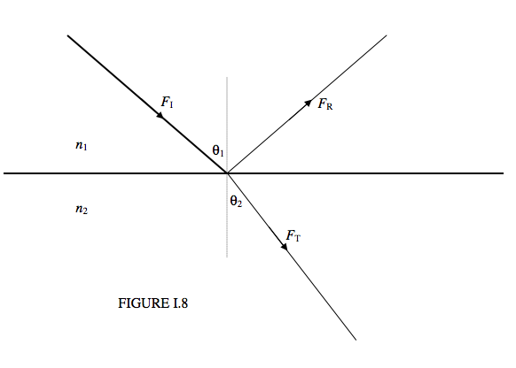
Figure I.8 shows an incident ray of energy flux density (W m−2 normal to the direction of propagation) \(F_I\) arriving at an interface between media of indices \(n_1\) and \(n_2\). It is subsequently divided into a reflected ray of flux density \(F_R\) and a transmitted ray of flux density \(F_T\). The fractions transmitted and reflected (\(t\) and \(r\)) are
\[ t = \frac{F_T}{F_I} = 2n_1n_2 \cos\theta_1\cos\theta_2\left( \frac{1}{(n_1\cos\theta_1+n_2\cos\theta_2)^2} + \frac{1}{(n_1\cos\theta_1+n_2\cos\theta_1)^2}\right) \label{eq:1.5.1} \]
and
\[ r = \frac{F_T}{F_I} =\frac{1}{2}\left[\left( \frac{n_1\cos\theta_1-n_2\cos\theta_2}{(n_1\cos\theta_1+n_2\cos\theta_2)^2}\right)^2 + \left(\frac{n_1\cos\theta_1-n_2\cos\theta_1}{(n_1\cos\theta_1+n_2\cos\theta_1)^2}\right)^2\right] \label{eq:1.5.2} \]
Here the angles and indices are related through Snell’s law, Equation 1.3.2. If you have the energy, show that the sum of these is 1. Both the transmitted and the reflected rays are partially plane polarized. If the angle of incidence and the refractive index are such that the transmitted and reflected rays are perpendicular to each other, the reflected ray is completely plane polarized – but such details need not trouble us in this chapter.
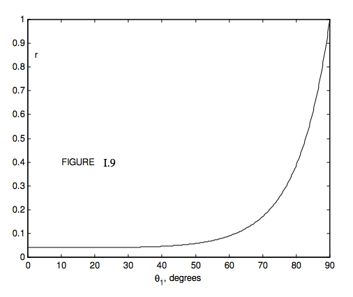
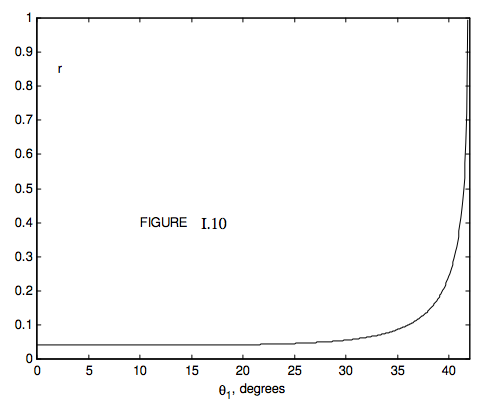
Figure I.9 shows the reflection coefficient as a function of angle of incidence for unpolarized incident light with \(n_1 = 1.0\) and \(n_2 = 1.5\) (e.g. glass). Since \(n_2 > n_1\), we have external reflection. We see that for angles of incidence less than about 45 degrees, very little of the light is reflected, but after this the reflection coefficient increases rapidly with angle of incidence, approaching unity as \( \theta_1\) → 90° (grazing incidence). If \(n_1 = 1.5\) and \(n_2 = 1.0\), we have internal reflection, and the reflection coefficient for this case is shown in Figure I.10. For internal angles of incidence less than about 35°, little light is reflected, the rest being transmitted. After this, the reflection coefficient increases rapidly, until the internal angle of incidence \(\theta_1\) approaches a critical angle \(C\), given by
\[ \sin C = \frac{n_2}{n_1},\label{eq:1.5.3} \]
This corresponds to an angle of emergence of 90°. For angles of incidence greater than this, the light is totally internally reflected. For glass of refractive index 1.5, the critical angle is 41°.2, so that light is totally internally reflected inside a 45° prism such as is used in binoculars.