
11.7: Equilibrium


- Last updated
- Mar 28, 2024
- Save as PDF
( \newcommand{\kernel}{\mathrm{null}\,}\)
In this section, we consider the conditions under which an object is in static or dynamic equilibrium. An object is in equilibrium if it does not rotate when viewed in a frame of reference where the object’s center of mass is stationary (or moving at constant velocity).
Static equilibrium
An object is in static equilibrium, if both the sum of the external forces exerted on the object and the sum of the external torques (about any axis) are zero. If the object is in static equilibrium the center of mass will have no acceleration and the object will have no angular acceleration. In the center of mass frame of reference, the object is immobile.
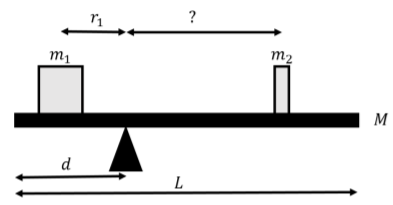
Two masses, m1 and m2 are placed on a balance as shown in Figure 11.7.1. The balance is made of a plank of mass M and length L that is placed on a fulcrum that is a distance d from one of the edges of the plank. If mass m1 is placed at a distance r1 from the fulcrum, how far should mass m2 be placed on the other side of the plank in order for the balance to be in equilibrium?
Solution
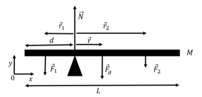
We can consider the plank as the object that is in static equilibrium. Thus, the sum of the forces and the sum of the torques on the plank must be zero. We first start by identifying the forces that are exerted on the plank; these are:
- →Fg, the weight of the plank, exerted at the center of mass of the plank.
- →F1, a force equal to the weight of mass m1, exerted at the location of m1.
- →F2, a force equal to the weight of mass m2, exerted at the location of m2.
- →N, a normal force exerted by the fulcrum.
The forces are illustrated in Figure 11.7.2 along with our choice of coordinate system. The z axis is not illustrated, and is directed out of the page.
All of the forces are in the y direction, so we only write the y component of Newton’s Second Law (with zero acceleration), which allows us to determine the magnitude of the normal force:
∑Fy=N−Mg−m1g−m2g=0∴N=(M+m1+m2)g
Because the plank is in static equilibrium, the sum of the torques must also be zero. We can choose the axis of rotation about which to calculate the torques. We choose an axis that is parallel to the z axis (out of the page) and goes through the fulcrum. In general, since we can choose the axis of rotation, it is usually convenient to choose an axis that goes through a point where at least one force is being exerted, because the torque from that force will be zero (its lever arm will be zero). Furthermore, since all of the forces are in the xy plane, the net torque on the plank will be in the z direction, so it makes sense to choose an axis in that direction.
The torques from the weight of the plank and from the force exerted by mass m2 will be in the negative z direction, and the torque from the force exerted by mass m1 will be in the positive z direction. The normal force will not result in any torque, because it is exerted at the axis of rotation and has a lever arm of zero.
We define →r1 as the vector from the fulcrum to mass m1. The torque, →τ1, from the force exerted by mass m1 is given by:
→τ1=→r1×→F1=(−r1ˆx)×(−F1ˆy)=r1F1(ˆx׈y)=r1F1ˆz=r1m1gˆz
where we used the fact that the magnitude of →F1 is m1g. Similarly, the torques from the force exerted by m2, →τ2, and by the weight, →τg, are given by:
→τ2=→r2×→F2=−m2gr2ˆz→τg=→r×→Fg=−rMgˆz=−(L2−d)Mgˆz
where L2−d is the distance between the fulcrum and where the weight of the plank is exerted. We require that the z component of the net torque be equal to zero (since all of the torques are in the z direction), which allows us to determine r2:
∑τz=τ1z+τ2z+τgz=0m1gr1−m2gr2−(L2−d)Mg=0∴r2=1m2(m1r1−(L2−d)M)
Note that because we chose to calculate the torques about a point that goes through the fulcrum, in this case, we did not need to determine the value of the normal force which we obtained from Newton’s Second Law.
Discussion
This example highlights the fact that when an object is in static equilibrium, we can choose a convenient axis about which to calculate the torques. In this case, by calculating the torques about the fulcrum, we did not need to consider the torque from the normal force. If we had chosen a different point, then the torque from the normal force would have been non-zero, and we would have used Newton’s Second Law to express the normal force in terms of the other quantities. Physically, if we had placed the fulcrum at the center of the plank d=L/2, then we would have found that m1r1=m2r2, the well known equation for a balance. This equation, of course, comes from requiring that the torques from the forces exerted by m1 and m2 are equal in magnitude and opposite in direction.
Dynamic equilibrium
Before proceeding, you may wish to review Section 5.6 on inertial forces.
When an object is in dynamic equilibrium, its center of mass is accelerating, but the object is not rotating when viewed from its center of mass frame of reference. Thus, the sum of the external forces exerted on the object is not zero, while the net external torque exerted on the object is zero, in the frame of reference of the center of mass.
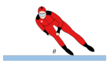
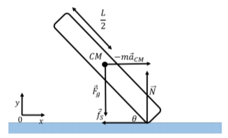
Consider, for example, a speed skater going around a circular track or radius R, and leaning into the center making an angle θ with the ice, as depicted in Figure 11.7.3. The skater’s center of mass is accelerating, because she is going around a circle, so the net force on the skater is not zero. However, in the reference frame of the skater, the skater is not rotating; she is thus in dynamic equilibrium.
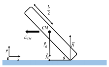
The forces on the skater are:
- →Fg, her weight, exerted at her center of mass with magnitude, Mg.
- →N, a normal force, exerted by the ice upwards on her skates.
- →fs, a force of static friction, exerted towards the center of the circle, by the ice on her skates.
The forces are illustrated in Figure 11.7.4 along with our choice of coordinate system.
The sum of the forces exerted on the skater must be towards the center of the circle and equal to the mass of the skater times her centripetal acceleration (which is the acceleration of her center of mass, →aCM). The x and y components of Newton’s Second Law are thus given by:
∑Fx=−fs=−maCM−mv2R∑Fy=N−mg=0
All of the forces exerted on the skater are in the xy plane, so we consider torques about an axis that is co-linear with the z axis. Consider the torques about an axis through the point of contact between the skates and the ice; there is a net torque in the counter-clockwise direction due to the weight of the skater (the weight is the only force that can result in a torque about the point of contact with the ice). We expect that the skater would topple over, however, this must not be a correct model for the skater, since we know that it is possible for her to lean in without falling.
Consider, instead, the sum of the torques about an axis through her center of mass. If the skater has a length L and the center of mass is in the middle of the skater, the sum of the torques about the center of mass is given by the torques from the normal forces and the force of friction:
∑τ=τNz+τfsz=L2cosθN−L2sinθfs
About the center of mass, the torques must be zero for the skater not to rotate, and this would give a relation between the force of static friction and the normal force.
Why do we get an incorrect model when we take the torques about the point of contact between the ice and the skater? In order to determine if the skater is rotating, we need to be in the same reference frame as the skater. However, the frame of reference of the skater is not an inertial frame of reference, since the skater is accelerating. We can still model the forces on the skater in the non-accelerating frame of reference, as long as we include the inertial force, −m→aCM, in that frame of reference. In the frame of reference of the skater, there is an additional inertial force, −m→aCM, in order for the sum of te forces to be zero (in the frame of reference of the skater, the sum of the forces must be zero since the skater is not accelerating in that frame of reference). The additional inertial force is exerted at the center of mass, as illustrated in Figure 11.7.5.
The reason that our model worked when taking the torques about the center of mass is that the inertial force, exerted at the center of mass, does not result in a torque (since it has a lever arm of zero). Our model was technically wrong, but if we take the torques about the center of mass, then we do not need to worry about the inertial force. If we include the additional inertial force, then we can take the torques about any point, just as in the static equilibrium case.