
3.4: Thin Lens Equation and Optical Instruments


- Last updated
- Nov 6, 2024
- Save as PDF

( \newcommand{\kernel}{\mathrm{null}\,}\)
Given the laws of reflection and refraction, one can see in principle how the passage of light through an optical instrument could be traced. For each of a number of initial rays, the change in the direction of the ray at each mirror surface or refractive index interface can be calculated. Between these points, the ray traces out a straight line.
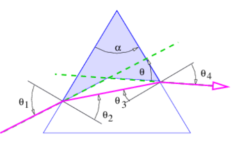
Though simple in conception, this procedure can be quite complex in practice. However, the procedure simplifies if a number of approximations, collectively called the thin lens approximation, are valid. We begin with the calculation of the bending of a ray of light as it passes through a prism, as illustrated in Figure 3.4.4:.
The pieces of information needed to find θ, the angle through which the ray is deflected, are as follows: the geometry of the triangle defined by the entry and exit points of the ray and the upper vertex of the prism leads to
α+(π/2−θ2)+(π/2−θ3)=π
which simplifies to
α=θ2+θ3
Snell’s law at the entrance and exit points of the ray tell us that
n=sin(θ1)sin(θ2)n=sin(θ4)sin(θ3)
where n is the index of refraction of the prism. (The index of refraction of the surroundings is assumed to be unity.) One can also infer that
θ=θ1+θ4−α
This comes from the fact that the the sum of the internal angles of the shaded quadrangle in Figure 3.4.4: is
(π/2−θ1)+α+(π/2−θ4)+(π+θ)=2π.
Combining equations (???), (???), and (???) allows the ray deflection θ to be determined in terms of θ1 and α, but the resulting expression is very messy. However, great simplification occurs if the following conditions are met:
- The angle α ≪ 1.
- The angles θ1, θ2, θ3, θ4 ≪ 1.
With these approximations it is easy to show that
θ=α(n−1)( small angles )
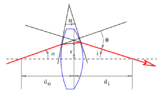
Generally speaking, lenses and mirrors in optical instruments have curved rather than flat surfaces. However, we can still use the laws for reflection and refraction by plane surfaces as long as the segment of the surface on which the wave packet impinges is not curved very much on the scale of the wave packet dimensions. This condition is easy to satisfy with light impinging on ordinary optical instruments. In this case, the deflection of a ray of light is given by equation (???) if α is defined as the intersection of the tangent lines to the entry and exit points of the ray, as illustrated in Figure 3.4.5:.
A positive lens is thicker in the center than at the edges. The angle α between the tangent lines to the two surfaces of the lens at a distance r from the central axis takes the form α=Cr, where C is a constant. The deflection angle of a beam hitting the lens a distance r from the center is therefore θ=Cr(n−1), as indicated in Figure 3.4.5:. The angles o and i sum to the deflection angle: o+i=θ=Cr(n−1). However, to the extent that the small angle approximation holds, o=r/do and i=r/di where do is the distance to the object and diis the distance to the image of the object. Putting these equations together and cancelling the r results in the thin lens equation:
1do+1di=C(n−1)≡1f
The quantity f is called the focal length of the lens. Notice that f=di if the object is very far from the lens, i. e., if do is extremely large.
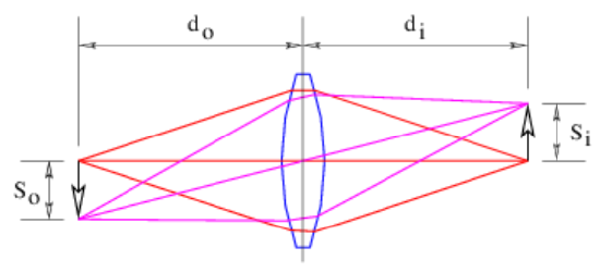
Figure 3.4.6: shows how a positive lens makes an image. The image is produced by all of the light from each point on the object falling on a corresponding point in the image. If the arrow on the left is an illuminated object, an image of the arrow will appear at right if the light coming from the lens is allowed to fall on a piece of paper or a ground glass screen. The size of the object So and the size of the image Si are related by simple geometry to the distances of the object and the image from the lens:
SiSo=dido
Notice that a positive lens inverts the image.
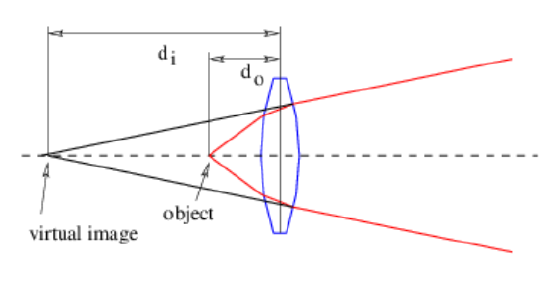
An image will be produced to the right of the lens only if do > f. If do < f, the lens is unable to converge the rays from the image to a point, as is seen in Figure 3.4.7:. However, in this case the backward extension of the rays converge at a point called a virtual image, which in the case of a positive lens is always farther away from the lens than the object. The image is called virtual because it does not appear on a ground glass screen placed at this point. Unlike the real image seen in Figure 3.4.6:, the virtual image is not inverted. The thin lens equation still applies if the distance from the lens to the image is taken to be negative.
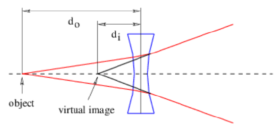
A negative lens is thinner in the center than at the edges and produces only virtual images. As seen in Figure 3.4.8:, the virtual image produced by a negative lens is closer to the lens than is the object. Again, the thin lens equation is still valid, but both the distance from the image to the lens and the focal length must be taken as negative. Only the distance to the object remains positive.
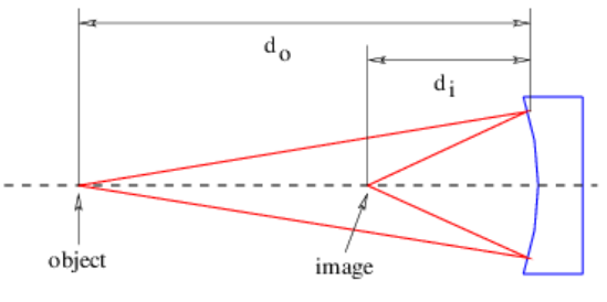
Curved mirrors also produce images in a manner similar to a lens, as shown in Figure 3.4.9:. A concave mirror, as seen in this figure, works in analogy to a positive lens, producing a real or a virtual image depending on whether the object is farther from or closer to the mirror than the mirror’s focal length. A convex mirror acts like a negative lens, always producing a virtual image. The thin lens equation works in both cases as long as the angles are small.