Physics LibreTexts

5.3: Conductors, Insulators, and Charging by Induction

  • Page ID
    4373
  • \( \newcommand{\vecs}[1]{\overset { \scriptstyle \rightharpoonup} {\mathbf{#1}} } \)

    \( \newcommand{\vecd}[1]{\overset{-\!-\!\rightharpoonup}{\vphantom{a}\smash {#1}}} \)

    \( \newcommand{\id}{\mathrm{id}}\) \( \newcommand{\Span}{\mathrm{span}}\)

    ( \newcommand{\kernel}{\mathrm{null}\,}\) \( \newcommand{\range}{\mathrm{range}\,}\)

    \( \newcommand{\RealPart}{\mathrm{Re}}\) \( \newcommand{\ImaginaryPart}{\mathrm{Im}}\)

    \( \newcommand{\Argument}{\mathrm{Arg}}\) \( \newcommand{\norm}[1]{\| #1 \|}\)

    \( \newcommand{\inner}[2]{\langle #1, #2 \rangle}\)

    \( \newcommand{\Span}{\mathrm{span}}\)

    \( \newcommand{\id}{\mathrm{id}}\)

    \( \newcommand{\Span}{\mathrm{span}}\)

    \( \newcommand{\kernel}{\mathrm{null}\,}\)

    \( \newcommand{\range}{\mathrm{range}\,}\)

    \( \newcommand{\RealPart}{\mathrm{Re}}\)

    \( \newcommand{\ImaginaryPart}{\mathrm{Im}}\)

    \( \newcommand{\Argument}{\mathrm{Arg}}\)

    \( \newcommand{\norm}[1]{\| #1 \|}\)

    \( \newcommand{\inner}[2]{\langle #1, #2 \rangle}\)

    \( \newcommand{\Span}{\mathrm{span}}\) \( \newcommand{\AA}{\unicode[.8,0]{x212B}}\)

    \( \newcommand{\vectorA}[1]{\vec{#1}}      % arrow\)

    \( \newcommand{\vectorAt}[1]{\vec{\text{#1}}}      % arrow\)

    \( \newcommand{\vectorB}[1]{\overset { \scriptstyle \rightharpoonup} {\mathbf{#1}} } \)

    \( \newcommand{\vectorC}[1]{\textbf{#1}} \)

    \( \newcommand{\vectorD}[1]{\overrightarrow{#1}} \)

    \( \newcommand{\vectorDt}[1]{\overrightarrow{\text{#1}}} \)

    \( \newcommand{\vectE}[1]{\overset{-\!-\!\rightharpoonup}{\vphantom{a}\smash{\mathbf {#1}}}} \)

    \( \newcommand{\vecs}[1]{\overset { \scriptstyle \rightharpoonup} {\mathbf{#1}} } \)

    \( \newcommand{\vecd}[1]{\overset{-\!-\!\rightharpoonup}{\vphantom{a}\smash {#1}}} \)

    \(\newcommand{\avec}{\mathbf a}\) \(\newcommand{\bvec}{\mathbf b}\) \(\newcommand{\cvec}{\mathbf c}\) \(\newcommand{\dvec}{\mathbf d}\) \(\newcommand{\dtil}{\widetilde{\mathbf d}}\) \(\newcommand{\evec}{\mathbf e}\) \(\newcommand{\fvec}{\mathbf f}\) \(\newcommand{\nvec}{\mathbf n}\) \(\newcommand{\pvec}{\mathbf p}\) \(\newcommand{\qvec}{\mathbf q}\) \(\newcommand{\svec}{\mathbf s}\) \(\newcommand{\tvec}{\mathbf t}\) \(\newcommand{\uvec}{\mathbf u}\) \(\newcommand{\vvec}{\mathbf v}\) \(\newcommand{\wvec}{\mathbf w}\) \(\newcommand{\xvec}{\mathbf x}\) \(\newcommand{\yvec}{\mathbf y}\) \(\newcommand{\zvec}{\mathbf z}\) \(\newcommand{\rvec}{\mathbf r}\) \(\newcommand{\mvec}{\mathbf m}\) \(\newcommand{\zerovec}{\mathbf 0}\) \(\newcommand{\onevec}{\mathbf 1}\) \(\newcommand{\real}{\mathbb R}\) \(\newcommand{\twovec}[2]{\left[\begin{array}{r}#1 \\ #2 \end{array}\right]}\) \(\newcommand{\ctwovec}[2]{\left[\begin{array}{c}#1 \\ #2 \end{array}\right]}\) \(\newcommand{\threevec}[3]{\left[\begin{array}{r}#1 \\ #2 \\ #3 \end{array}\right]}\) \(\newcommand{\cthreevec}[3]{\left[\begin{array}{c}#1 \\ #2 \\ #3 \end{array}\right]}\) \(\newcommand{\fourvec}[4]{\left[\begin{array}{r}#1 \\ #2 \\ #3 \\ #4 \end{array}\right]}\) \(\newcommand{\cfourvec}[4]{\left[\begin{array}{c}#1 \\ #2 \\ #3 \\ #4 \end{array}\right]}\) \(\newcommand{\fivevec}[5]{\left[\begin{array}{r}#1 \\ #2 \\ #3 \\ #4 \\ #5 \\ \end{array}\right]}\) \(\newcommand{\cfivevec}[5]{\left[\begin{array}{c}#1 \\ #2 \\ #3 \\ #4 \\ #5 \\ \end{array}\right]}\) \(\newcommand{\mattwo}[4]{\left[\begin{array}{rr}#1 \amp #2 \\ #3 \amp #4 \\ \end{array}\right]}\) \(\newcommand{\laspan}[1]{\text{Span}\{#1\}}\) \(\newcommand{\bcal}{\cal B}\) \(\newcommand{\ccal}{\cal C}\) \(\newcommand{\scal}{\cal S}\) \(\newcommand{\wcal}{\cal W}\) \(\newcommand{\ecal}{\cal E}\) \(\newcommand{\coords}[2]{\left\{#1\right\}_{#2}}\) \(\newcommand{\gray}[1]{\color{gray}{#1}}\) \(\newcommand{\lgray}[1]{\color{lightgray}{#1}}\) \(\newcommand{\rank}{\operatorname{rank}}\) \(\newcommand{\row}{\text{Row}}\) \(\newcommand{\col}{\text{Col}}\) \(\renewcommand{\row}{\text{Row}}\) \(\newcommand{\nul}{\text{Nul}}\) \(\newcommand{\var}{\text{Var}}\) \(\newcommand{\corr}{\text{corr}}\) \(\newcommand{\len}[1]{\left|#1\right|}\) \(\newcommand{\bbar}{\overline{\bvec}}\) \(\newcommand{\bhat}{\widehat{\bvec}}\) \(\newcommand{\bperp}{\bvec^\perp}\) \(\newcommand{\xhat}{\widehat{\xvec}}\) \(\newcommand{\vhat}{\widehat{\vvec}}\) \(\newcommand{\uhat}{\widehat{\uvec}}\) \(\newcommand{\what}{\widehat{\wvec}}\) \(\newcommand{\Sighat}{\widehat{\Sigma}}\) \(\newcommand{\lt}{<}\) \(\newcommand{\gt}{>}\) \(\newcommand{\amp}{&}\) \(\definecolor{fillinmathshade}{gray}{0.9}\)
    Learning Objectives

    By the end of this section, you will be able to:

    • Explain what a conductor is
    • Explain what an insulator is
    • List the differences and similarities between conductors and insulators
    • Describe the process of charging by induction

    In the preceding section, we said that scientists were able to create electric charge only on nonmetallic materials and never on metals. To understand why this is the case, you have to understand more about the nature and structure of atoms. In this section, we discuss how and why electric charges do—or do not—move through materials (Figure \(\PageIndex{1}\)). A more complete description is given in a later chapter.
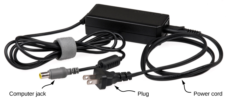
    A photograph of a black power charging unit that connects a laptop to an electrical outlet, allowing the laptop to be charged.
    Figure \(\PageIndex{1}\): This power adapter uses metal wires and connectors to conduct electricity from the wall socket to a laptop computer. The conducting wires allow electrons to move freely through the cables, which are shielded by rubber and plastic. These materials act as insulators that don’t allow electric charge to escape outward. (credit: modification of work by “Evan-Amos”/Wikimedia Commons)

    Conductors and Insulators

    As discussed in the previous section, electrons surround the tiny nucleus in the form of a (comparatively) vast cloud of negative charge. However, this cloud does have a definite structure to it. Let’s consider an atom of the most commonly used conductor, copper.

    For reasons that will become clear in Atomic Structure, there is an outermost electron that is only loosely bound to the atom’s nucleus. It can be easily dislodged; it then moves to a neighboring atom. In a large mass of copper atoms (such as a copper wire or a sheet of copper), these vast numbers of outermost electrons (one per atom) wander from atom to atom, and are the electrons that do the moving when electricity flows. These wandering, or “free,” electrons are called conduction electrons, and copper is therefore an excellent conductor (of electric charge). All conducting elements have a similar arrangement of their electrons, with one or two conduction electrons. This includes most metals.

    Insulators, in contrast, are made from materials that lack conduction electrons; charge flows only with great difficulty, if at all. Even if excess charge is added to an insulating material, it cannot move, remaining indefinitely in place. This is why insulating materials exhibit the electrical attraction and repulsion forces described earlier, whereas conductors do not; any excess charge placed on a conductor would instantly flow away (due to mutual repulsion from existing charges), leaving no excess charge around to create forces. Charge cannot flow along or through an insulator, so its electric forces remain for long periods of time. (Charge will dissipate from an insulator, given enough time.) As it happens, amber, fur, and most semi-precious gems are insulators, as are materials like wood, glass, and plastic.

    Charging by Induction

    Let’s examine in more detail what happens in a conductor when an electrically charged object is brought close to it. As mentioned, the conduction electrons in the conductor are able to move with nearly complete freedom. As a result, when a charged insulator (such as a positively charged glass rod) is brought close to the conductor, the (total) charge on the insulator exerts an electric force on the conduction electrons. Since the rod is positively charged, the conduction electrons (which themselves are negatively charged) are attracted, flowing toward the insulator to the near side of the conductor (Figure \(\PageIndex{2}\)).

    Now, the conductor is still overall electrically neutral; the conduction electrons have changed position, but they are still in the conducting material. However, the conductor now has a charge distribution; the near end (the portion of the conductor closest to the insulator) now has more negative charge than positive charge, and the reverse is true of the end farthest from the insulator. The relocation of negative charges to the near side of the conductor results in an overall positive charge in the part of the conductor farthest from the insulator. We have thus created an electric charge distribution where one did not exist before. This process is referred to as inducing polarization—in this case, polarizing the conductor. The resulting separation of positive and negative charge is called polarization, and a material, or even a molecule, that exhibits polarization is said to be polarized. A similar situation occurs with a negatively charged insulator, but the resulting polarization is in the opposite direction.
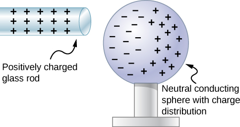
    A microscopic view of polarization is shown. A positively charged glass rod with positive signs is close to a neutral conducting sphere with a charge distribution. The negative charges on the sphere are on the side near the rod and positive charges are on the side opposite from the rod.
    Figure \(\PageIndex{2}\): Induced polarization. A positively charged glass rod is brought near the left side of the conducting sphere, attracting negative charge and leaving the other side of the sphere positively charged. Although the sphere is overall still electrically neutral, it now has a charge distribution, so it can exert an electric force on other nearby charges. Furthermore, the distribution is such that it will be attracted to the glass rod.

    The result is the formation of what is called an electric dipole, from a Latin phrase meaning “two ends.” The presence of electric charges on the insulator—and the electric forces they apply to the conduction electrons—creates, or “induces,” the dipole in the conductor.

    Neutral objects can be attracted to any charged object. The pieces of straw attracted to polished amber are neutral, for example. If you run a plastic comb through your hair, the charged comb can pick up neutral pieces of paper. Figure \(\PageIndex{3}\) shows how the polarization of atoms and molecules in neutral objects results in their attraction to a charged object.

    Microscopic views of objects are shown. In part a, a positive rod with positive signs is close to an insulator. The negative ends of all the molecules of the insulator are aligned toward the rod and positive ends of all molecules shown as spheres are away from the rod. In part b, a negative rod with negative signs is close to an insulator. The positive ends of all the molecules of the insulator are aligned toward the rod and negative ends of all molecules shown as spheres are away from the rod. In part c, a rod with negative signs is close to an insulator. Only the net charges are shown in the insulator. The insulator surface closer to the rod has positive signs. The other surface has negative signs.
    Figure \(\PageIndex{3}\): Both positive and negative objects attract a neutral object by polarizing its molecules. (a) A positive object brought near a neutral insulator polarizes its molecules. There is a slight shift in the distribution of the electrons orbiting the molecule, with unlike charges being brought nearer and like charges moved away. Since the electrostatic force decreases with distance, there is a net attraction. (b) A negative object produces the opposite polarization, but again attracts the neutral object. (c) The same effect occurs for a conductor; since the unlike charges are closer, there is a net attraction.

    When a charged rod is brought near a neutral substance, an insulator in this case, the distribution of charge in atoms and molecules is shifted slightly. Opposite charge is attracted nearer the external charged rod, while like charge is repelled. Since the electrostatic force decreases with distance, the repulsion of like charges is weaker than the attraction of unlike charges, and so there is a net attraction. Thus, a positively charged glass rod attracts neutral pieces of paper, as will a negatively charged rubber rod. Some molecules, like water, are polar molecules. Polar molecules have a natural or inherent separation of charge, although they are neutral overall. Polar molecules are particularly affected by other charged objects and show greater polarization effects than molecules with naturally uniform charge distributions.

    When the two ends of a dipole can be separated, this method of charging by induction may be used to create charged objects without transferring charge. In Figure \(\PageIndex{4}\), we see two neutral metal spheres in contact with one another but insulated from the rest of the world. A positively charged rod is brought near one of them, attracting negative charge to that side, leaving the other sphere positively charged.
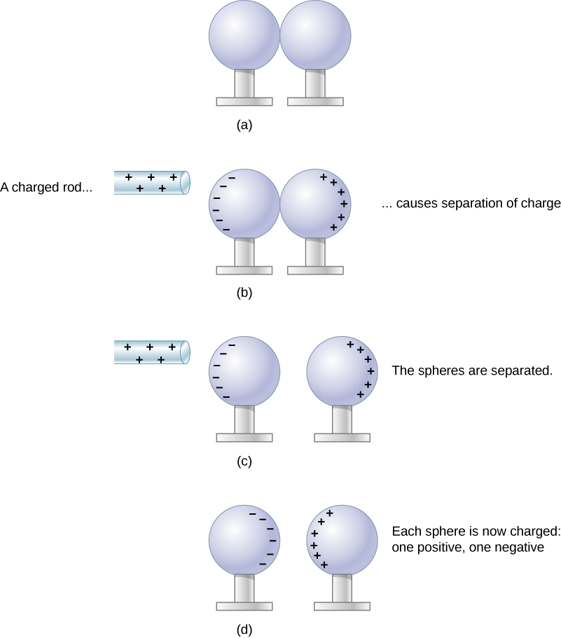
    In part a, a pair of neutral metal spheres are in contact. In part b, a rod with positive charge is close to the surface of one of the sphere. Negative signs are shown on this surface near the rod and positive signs are shown on the farthest part of the surface of the other sphere. The charged rod causes separation of charge. In part c, the positively charged rod is near the spheres, and the spheres are not in contact. As in figure b, the outer surface of the sphere nearest the rod has negative signs and the far surface of the other sphere has positive signs. In part d, the glass rod is not shown. The charges are now on the inner surfaces of the metallic spheres. One sphere has negative signs and the other has positive signs facing each other.
    Figure \(\PageIndex{4}\): Charging by induction. (a) Two uncharged or neutral metal spheres are in contact with each other but insulated from the rest of the world. (b) A positively charged glass rod is brought near the sphere on the left, attracting negative charge and leaving the other sphere positively charged. (c) The spheres are separated before the rod is removed, thus separating negative and positive charges. (d) The spheres retain net charges after the inducing rod is removed—without ever having been touched by a charged object.

    Another method of charging by induction is shown in Figure \(\PageIndex{5}\). The neutral metal sphere is polarized when a charged rod is brought near it. The sphere is then grounded, meaning that a conducting wire is run from the sphere to the ground. Since Earth is large and most of the ground is a good conductor, it can supply or accept excess charge easily. In this case, electrons are attracted to the sphere through a wire called the ground wire, because it supplies a conducting path to the ground. The ground connection is broken before the charged rod is removed, leaving the sphere with an excess charge opposite to that of the rod. Again, an opposite charge is achieved when charging by induction, and the charged rod loses none of its excess charge.
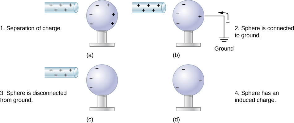
    In part a, a rod with positive sign is brought near a neutral metal sphere. The surface of the sphere near the rod has negative signs and the surface far from it has positive signs. In part b, the sphere is connected to ground by a wire attached to the surface farthest from the rod. Negative charge is shown moving from the ground up to the sphere. The negative charges on the sphere near the rod are unaffected but there are fewer positive charges where the sphere is grounded. In part c, the sphere is disconnected from ground. The rod with positive sign is close to one surface of the sphere where negative charges are shown, and the other surface has no charges shown. In part d, the positive rod is absent, and the sphere has negative signs on it uniformly distributed on its surface.
    Figure \(\PageIndex{5}\): Charging by induction using a ground connection. (a) A positively charged rod is brought near a neutral metal sphere, polarizing it. (b) The sphere is grounded, allowing electrons to be attracted from Earth’s ample supply. (c) The ground connection is broken. (d) The positive rod is removed, leaving the sphere with an induced negative charge.

    This page titled 5.3: Conductors, Insulators, and Charging by Induction is shared under a CC BY 4.0 license and was authored, remixed, and/or curated by OpenStax via source content that was edited to the style and standards of the LibreTexts platform.